


Chapter 5 Equipment
MDC-900 Series
5-14
0093142132-05
After confirming the above items, be sure to perform the adjustments.
The adjustments after the installation are the following items in 3.3 Setup of Adjustment Items.
BRG
ADJ
TX
DELAY
ADJ
MBS
AUTO
TUNE
ADJ
5.5
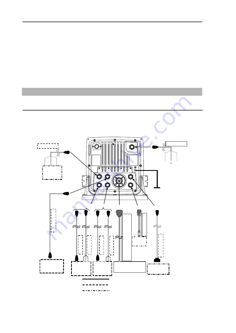
Wiring
Cable connection to the Display unit
Connect the power cable, antenna cable and cables of others to specified connectors of the display
unit. If optional navigation equipment and CCD camera are provided, connect also the cables of these
equipments.
To J3
To J2
To J1
To J4
To J5
To J7
to J6
receiver
AIS
+
GND
10.8 - 31.2 VDC
Wh
ite
Black
Gray
Display unit MRD-103
: Standard product
: Optional product
: Product prepared by a user
CW-265-2M
CW
-576-0.5M
CW
-405-0.3M
CW
-561-10M
CW-376-5M
Antenna - scanner
unit
GND
To POWER
Remote
display
Navigation
equipment
Navigation
equipment
External
monitor
CCD
camera
* Be sure to connect the KGC-1 to J4.
Slave
CW
-373-5M
CW
-376-5M
CW
-376-5M
CW
-373-5M
To J3
To J4
To J5
To J7
To J6
CCD
camera
242J160680A-1
0
M
(for RB
714A)
242J158055A-1
0
M
(for RB
715A)
242J159098A-1
0
M
(
for RB
716A
)
Summary of Contents for MDC-900 Series
Page 1: ......
Page 2: ......
Page 72: ...Chapter 6 Attached Table MDC 900 Series 6 2 0093142132 05 ...
Page 75: ...MDC 900 Series Chapter 6 Attached Table 0093142132 05 6 5 6 3 External View ...
Page 83: ......


