KGC-222 System Configuration
0093822202-01
xi
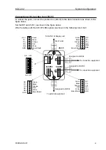
Connection with Junction box (JB-35)
To extend the ports, connect the junction box (JB-35) to the data connectors as shown in the
figure below.
Set the DIP switch (S1) as shown in the figure below.
Wire the cables with the CW-376-5M (option) as shown in the following color chart.
CW-376-5M
To DATA1 of Display unit
SLAVE1
SLAVE3
MASTER
SLAVE2
Green
Black
Orange
Red
White
Blue+Shield
+12V
TX-
TX+
RX-
RX+
GND
Green
Black
Orange
Red
White
Blue+Shield
NC
TX-
TX+
RX-
RX+
GND
S1
ALL OFF
To connection equipment
Assigned to DATA4
To connection equipment
Assigned to DATA5
Assigned to DATA1
To external equipment
JB-35
Green
Black
Orange
Red
White
Blue+Shield
NC
TX-
TX+
RX-
RX+
GND
Green
Black
Orange
Red
White
Blue+Shield
NC
TX-
TX+
RX-
RX+
GND
ON
OFF
1
2 3
4 5
6
7 8


