background image

Kodak Dental Imaging Software Overview

3–10

  IMAGING SOFTWARE OVERVIEW

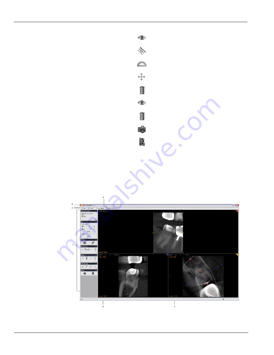
To access the 

Curved Slicing Window

, from the 

Home Page

 click the 

Curved Slicing Window


tab.

Figure 3–5

Curved Slicing Window

Measurements

Click 

 to show or hide measurements.

Click 

 to measure the length.

Click 

 to measure the angle.

Click 

 to edit the measurements.

Click 

 to delete the measurements.

Implant

Click 

 to show or hide all implants.

Click 

 to delete all implants.

Export

Click 

 to create a screen capture file.

Click 

 to access the screen capture file in the directory.

4

Display options: 

Display the specific screen in different formats.

1

Title  Bar:

 Displays software name and version.

Summary of Contents for Ngenuity 9000 Series

Page 1: ...KODAK 9000 3D Extraoral Imaging System User Guide...

Page 2: ...ze yourself with this Guide in order to make the most effective use of your system The information contained in this Guide may be subject to modification without notice justification or notification t...

Page 3: ...e 3 2 Kodak Dental Imaging Software Overview 3 3 Patient Window Overview 3 3 Imaging Window Overview 3 5 3D Imaging Windows Overview 3 8 Acquisition Interface Module 3 14 Panoramic Acquisition Window...

Page 4: ...g 5 11 6 MAINTENANCE Daily 6 1 Monthly 6 1 Annually 6 2 7 TECHNICAL SPECIFICATIONS Compliance with International Standards 7 1 Manufacturer 7 1 Model 7 1 Compliance with International Regulations 7 1...

Page 5: ...tion or indicate potential risk to personnel or equipment WARNING Warns you to avoid injury to yourself or others by following the safety instructions precisely CAUTION Alerts you to a condition that...

Page 6: ...at least 12db the frequency interferences of the 30MHz to 1GHz band Your local representative will assist you in the initial use of your radiology Unit and will supply any relevant information you ma...

Page 7: ...avoid direct light reflections from internal or external lighting DO NOT operate the Unit if there is the threat of an earthquake Following an earthquake ensure that the Unit is operating satisfactori...

Page 8: ...ur local sales representative for additional information on the collection and recovery programs available for this product WARNING and IONIZING RADIATION symbols warn you about radiation dangers LASE...

Page 9: ...to carry out the following radiological examinations Panoramic Maxillary Sinus Temporomandibular Joints TMJ 3D images The KODAK 9000 3D Unit is composed of the following functional components Control...

Page 10: ...ponents 1 ON OFF button 6 Temple supports 2 Unit fixed arm 7 Sensor 3 Control panel 8 Generator 4 Hand Grips 9 Unit rotative arm 5 Chin rest base 10 X Ray remote control 5 a Panoramic chin rest 11 PC...

Page 11: ...de SM710 _Ed 01 2 3 Figure 2 3 KODAK 9000 3D Unit Positioning Laser Beam components 1 3D central positioning laser beam 2 Mid sagittal positioning laser beam 3 Horizontal positioning laser beam 4 3D F...

Page 12: ...correctly position the patient for 3D acquisition 4 Laser Beam button Activates the beams to correctly position the patient 5 3D Position Verification button Verifies the correct 3D positioning 6 Rese...

Page 13: ...mote control enables you to launch a radiological image acquisition via the exposure button from outside the x ray room You must press and hold the exposure button until the end of acquisition Prematu...

Page 14: ...delivered with the KODAK 9000 3D digital imaging unit Table 2 1 Panoramic Positioning Accessories and Replacement Parts Accessory Description Panoramic chin rest TMJ x2 Sinus TMJ x4 nose rest Panorami...

Page 15: ...uo Core 3 GHz Intel Pentium 4 RAM 2 GB 2GB RAM has a major impact on system performance Hard disk drive 1 2 GB for software installation 80 GB free space to use the software 1 2 GB for software instal...

Page 16: ...isition interface module is a user friendly working interface that was designed and developed specifically for Kodak 9000 3D extraoral imaging system The Acquisition interface module has the following...

Page 17: ...t record management interface that provides you with all the patient record functions Figure 3 1 Patient Window 1 Title Bar Displays Software name Software version Practitioner name 2 Menu Bar Provide...

Page 18: ...before the given date Options Preferences Configures the language and the database location Toolbar Hides or shows the toolbar Help topics Displays the online contextual help About Lists the followin...

Page 19: ...Software name Software version Practitioner name Patient name 2 Menu Bar Provides access to the following functions 3 Toolbar Provides quick access to the following menu functions Menu Submenu Descrip...

Page 20: ...Paste Pastes selected image Send to Sends the selected image either via e mail or to a selected folder Exit Exits the Imaging Window Context Save context Saves the current images and screen display O...

Page 21: ...e Displays License information About Displays Kodak dental imaging software version information 4 Dental Arch Pane Displays the existing teeth images of the patient dental arch To open different histo...

Page 22: ...he indicated Windows 3 General Information Displays the 3D image acquisition information 4 Context Enables you to manage the patient 3D image analyses files Click to create a new analyses file Click t...

Page 23: ...o the following functions Menu Submenu Description General Information Displays the 3D image acquisition information MPR MultiPlanar Reformat Adjustment Adjusts the slices contrast and brightness Posi...

Page 24: ...hide measurements Click to measure the length Click to measure the angle Click to edit the measurements Click to delete the measurements Implant Click to show or hide all implants Click to delete all...

Page 25: ...k to configure the smooth filter settings Measurements Click to show or hide measurements Click to measure the length Click to measure the angle Click to edit the measurements Click to delete the meas...

Page 26: ...windows 3 Menu bar Provides access to the following functions Menu Submenu Description General Information Displays the 3D image acquisition information MPR MultiPlanar Reformat Adjustment Adjusts th...

Page 27: ...to delete the measurements Implant Click to show or hide all implants Click to delete all implants Crop Click to show or hide the crop tool Export Click to create a screen capture file Click to access...

Page 28: ...oftware version The default parameters set by the manufacturer 2 Preview Screen Displays the acquired image in real time 3 Selected Parameter Display Displays the current acquisition parameter setting...

Page 29: ...options 8 Ready Indicator LED Green indicates the Unit is ready to start acquisition Black indicates the Unit is not ready to start acquisition 9 Exit button Closes the Acquisition Window 10 X Ray Emi...

Page 30: ...ing to the right side of the patient Click on a section of the jaw to select an anatomical zone for radiological exam The selected segment is highlighted Figure 3 8 Panoramic Program Pane 1 Radiologic...

Page 31: ...ameters must be based on the patient age and morphology Figure 3 9 Panoramic Patient Pane 1 Patient corpulence parameters Click if the patient is a child Click if the patient is small Click if the pat...

Page 32: ...les you to choose exposure parameters for the radiological image acquisition You must adapt the parameter settings to the patient type Figure 3 10 Panoramic Parameter Pan 1 Fine tuning buttons Click t...

Page 33: ...elected Parameter Display Displays the current acquisition parameter settings 4 System Status Screen Displays various alert or warning messages originating from the Unit 5 X Rays ON OFF button Turns o...

Page 34: ...rameter options Parameters pane Exposure parameter options 10 Exit button Closes the Acquisition Window 11 X Ray Emission Indicator Yellow indicates the x ray emission status 12 Selector button Select...

Page 35: ...s The diagram in the Program pane represents the jaw Figure 3 12 3D Program Pane 1 Manual Selection Indicator Enables you to select the region of interest manually 2 Rotative Arm Position Indicator In...

Page 36: ...patient age and morphology Figure 3 13 Panoramic Patient Pane 1 Patient corpulence parameters Click if the patient is a child Click if the patient is small Click if the patient is medium Click if the...

Page 37: ...The 3D Parameter pane enables you to choose exposure parameters for the radiological image acquisition You must adapt the parameter settings to the patient type Figure 3 14 3D Parameter Pane 1 Fine tu...

Page 38: ...Acquisition Interface Module 3 24 IMAGING SOFTWARE OVERVIEW...

Page 39: ...roperly connected The PC is turned ON To start your imaging software follow these steps 1 On your desktop double click OR From your PC click Start All Programs Kodak Kodak Dental Software Blank Patien...

Page 40: ...k to access the Panoramic Acquisition Window or click to access the 3D Acquisition Window 2 Prepare the acquisition parameters and launch an acquisition Switching On the Unit Before switching on the U...

Page 41: ...ps 1 In the Panoramic Acquisition Window click the Program button to access the Program pane Click on the section of the jaw to select the anatomical zone for the x ray image such as panoramic TMJ x2...

Page 42: ...e patient to enter the Unit On the Control Panel press and hold to adjust the Unit to the patient height 4 Ask the patient to do the following NOTE If the patient is too tall ask the patient to sit on...

Page 43: ...agittal 1 positioning laser beam for a vertical alignment The horizontal 2 positioning laser beam for a Frankfurt plane alignment 6 Immobilize the patient head with the temple supports 3 NOTE You can...

Page 44: ...ntact with the palate and to breath through the nose Launching the X ray To launch the x ray follow these steps 1 Leave the x ray room and close the door You must keep eye contact with the patient dur...

Page 45: ...mission The image appears on the Preview Screen of the Panoramic Acquisition Window When the acquisition ends the Panoramic Acquisition Window disappears and the acquired image is automatically transf...

Page 46: ...nd cover it with a hygienic barrier 3 Press and hold to raise the chin rest to the maximum height 4 Correctly position the patient using the 2 positioning laser beams 5 Ask the patient to remain still...

Page 47: ...ogram pane Select the region of interest and click to validate the selection or click to cancel the modifications 2 Click the Patient button to access the Patient pane Select the patient Corpulence De...

Page 48: ...ool Grip the lower handle on each side Position the feet slightly forward Relax the shoulders for full motion of the Unit rotating Arm 5 Position the patient head in the 3D head support Ask the patien...

Page 49: ...tioning laser beam The 3D FoV 2 positioning laser beam 7 Press and hold to align the upper or lower jaw with the 3D FoV 2 positioning laser beam Tighten the temple supports 3 8 Ask the patient to clos...

Page 50: ...cquisition The turns yellow indicating x ray emission The image appears in the Preview Screen When the acquisition ends the 3D Acquisition Window disappears 3 Open the 3D head support and release the...

Page 51: ...sk the patient to bite into a plate of dental plaster and wait for the plaster imprint to harden 3 Place the dental imprint on the bite block location Press and hold to align the Unit rotative arm to...

Page 52: ...Acquiring a 3D Image 5 12 ACQUIRING IMAGES...

Page 53: ...ntal distributors Follow the disinfectant product manufacturer recommendations for safety precautions Table 6 1 Daily Maintenance Tasks Accessories Maintenance Tasks 3D and Panoramic bite block Steril...

Page 54: ...Annually 6 2 MAINTENANCE Annually We recommend a general inspection of the Unit carried out by an authorized service technician...

Page 55: ...l Regulations Medical Device directives 93 42 European Economic Community EEC Class II b ElectroMagnetic Compatibility EMC directive 89 336 EEC Compliance with International Standards International El...

Page 56: ...eq Al 3D Modality Technology Digital Volumetric Tomography DVT NA Sensor technology CMOS Optical fiber sensor with Csi coating NA Gray scale 16384 14 bits NA Volume size 50 x 37 mm NA Voxel size 76 5...

Page 57: ...1 7 3 Input voltage 230 240 V 50 60 Hz 100 110 130 V 50 60 Hz Unit dimensions 1158mm L x 1595mm D x 2378mm H Unit with shorter column is available on special order Required space 1500 L x 2000 D x 240...

Page 58: ...esponding tube current 10 mA 10 mA Nominal tube current 15 mA 15 mA Maximum corresponding high voltage 80 kV 68 kV Tube current voltage combination for maximum output power 80 kV 15 mA 85 kV 12 mA Nom...

Page 59: ...ompliance IEC 60601 1 3 Compliant Nominal value of the inherent filtration at 70 kV 2 5 mm 0 10 eq Al Nominal value of the supplementary filtration at 70 kV NA Nominal value of the total filtration at...

Page 60: ...um symmetrical field of radiation at a distance of 690 mm from the focal point 3D mode 47 1 x 59 1 mm Table 7 5 Characteristics of the X ray Tube Manufacturer s name CEI Type OPX 105 Nominal high volt...

Page 61: ...cifications KODAK 9000 3D Extraoral Imaging System_User Guide SM710 _Ed 01 7 7 Figure 7 2 Heating and Cooling Curves of the X ray Tube Figure 7 3 Single Load Chart of the X ray Tube Figure 7 4 Filamen...

Page 62: ...X Ray Generator Technical Specifications 7 8 TECHNICAL SPECIFICATIONS...

Reviews: