MISCELLANEOUS PUBLICATION
8
18JUL97 – XP3210-006
[10] De-energize the LASER PRINTER or IMAGE
MANAGER.
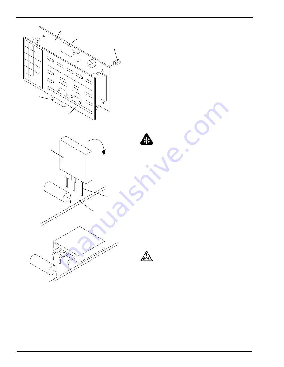
[11] Loosen and remove the plastic BUSHINGS from
the back of the CIRCUIT BOARD. Keep the
BUSHINGS.
[12] Separate the KEYPAD OVERLAY from the
CIRCUIT BOARD. Be careful not to damage the
RIBBON CABLE between them.
[13] Remove the solder from the pins connecting the
DC-DC CONVERTER to the CIRCUIT BOARD.
Important
Two of the pins on the DC-DC CONVERTER are
wider at one end and the third pin is uniformly narrow.
Insert the narrow pin into the hole at the edge of the
BOARD.
[14] Insert the pins of the new DC-DC CONVERTER
through the correct holes in the CIRCUIT
BOARD.
[15] Solder the pins of the DC-DC CONVERTER to
the CIRCUIT BOARD.
[16] Remove the paper from the adhesive pad on the
back of the DC-DC CONVERTER.
[17] Bend the pins and press the DC-DC
CONVERTER so that the adhesive pad adheres to
the CIRCUIT BOARD.
Caution
Be careful not to cause a short circuit between the pins.
[18] Energize the LASER PRINTER or IMAGE
MANAGER.
H027_2519AC
CABLE
RIBBON
OVERLAY
KEYPAD
DC-DC CONVERTER
CIRCUIT BOARD
BUSHINGS
H027_2519ACA
H027_2520GC
PINS
BOARD
CIRCUIT
CONVERTER
DC-DC
H027_2520GCA


