


8 6 0 1 0 8 • Q
MAIN: 816-753-2150
TOLL FREE: 800-777-5624
INTERNET: kochequipment.com
E-MAIL: [email protected]
M A I N T E N A N C E • P A G E 4 . 4
Troubleshooting
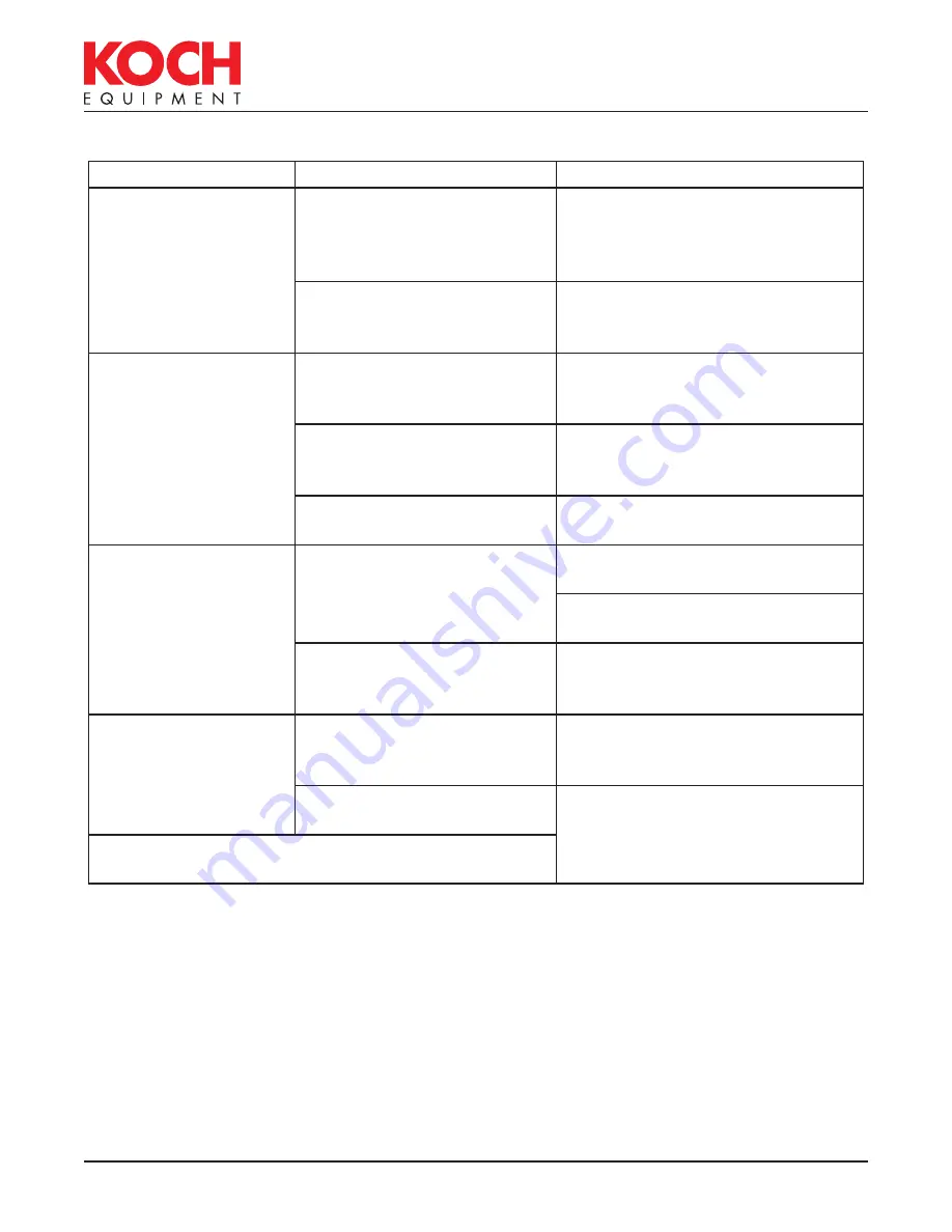
Problem
Indications
Remedy
Machine will not start
Green power “ON” light not
lit when switch is turned on
Make sure that the power
requirements match those given
on the nameplate. Also, check
fuse F-2; replace if blown.
Vacuum pump does not run
Make sure that the power
requirements match those given
on the nameplate
No vacuum
When lid is closed, indicator
light (VAC) is “OFF” on the
control module
Check lid switches LS-1 for proper
adjustment
Vacuum not pulling lid down Check intake screen in vacuum
pump hose barb for blockage,
pieces of bags, labels, bone, etc.
Longer vacuum cycle times
Check intake screen in vacuum
pump hose barb for blockage
No gas flush (optional) If indicator light (GAS) is lit
Check for proper gas pressure
going into gas inlet
Check for proper operation of gas
flush valve (SOL-3)
If indicator light (GAS) is not
lit
Check gas flush potentiometer on
analog control module or possible
defective digital control panel
Chamber not venting
(lid will not open)
Lid will not open and red
indicator light “VENT” on
control module is lit
Check ventilation valve SOL-1 for
proper operation
“VENT” indicator light is not
lit
Check cool down potentiometer
on analog control module or
possible defective digital control
panel
NOTE:
Lid can be released by pulling the hose off of
the vacuum gauge to remove product.


