


LFM
LFM K03/0422
Page 5
6. Mechanical connection
Please ensure that the permitted values of maximum pressure and
temperature are not exceeded.
The recommended filter size is 40µm.
The flowmeter should be installed vertically with flow from bottom to top.
Fibrous seals should be avoided as pieces can cause damage to the unit if
they enter the flowmeter. Connection should only be made using a correct fit-
ting and appropriate seal.
We recommend that you pressure test the unit for leaks after installation.
7. Electrical connection
When wiring the plug or making electrical connections to the flowmeter please
ensure that the power supply is isolated.
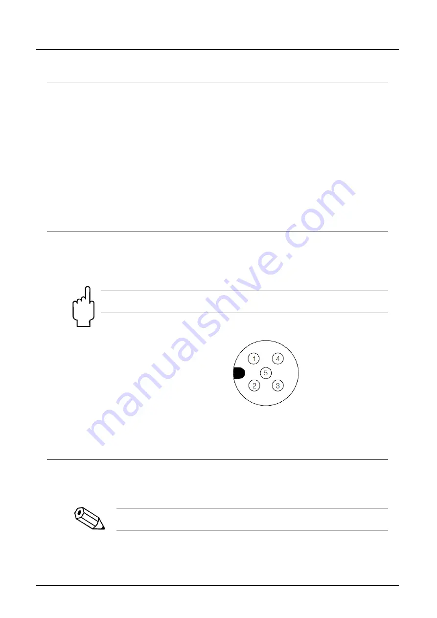
Electrical connections should be made according to the diagram.
Attention! Incorrect wiring may cause damage to the electronics.
Check!
Plug-Connector
5-pin plug M12 SPEEDCON
1 = +U
B
2 = n.c./NAMUR- (“N”, “U”)
3 = 0 V (not “N”)
4 = Signal Push-Pull (not “N”)
5 = n.c.
8. Operation
Please pay attention to the technical data printed on the type-label as well as
given in the data sheets.
The system must be evacuated from air otherwise the accuracy
will be affected.