background image

3

Contents

Safety and Environment Guidelines                                                                                             4

1  Introduction                                                                                                                            5


1.1 

Service Intervals   .    .    .    .    .    .    .    .    .    .    .    .    .    .    .    .    .    .    .    .     5


1.2 

Basic Principles    .    .    .    .    .    .    .    .    .    .    .    .    .    .    .    .    .    .    .    .     6 

2  Components                                                                                                                            9


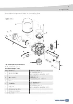
Serviceable Components of the Air Processing Unit  .    .    .    .    .    .    .    .    .    .    .    .    9

3   Service Instructions                                                                                                                                                                             10


3.1 

Removal and Replacement of the Desiccant Cartridge (A)   .    .    .    .    .    .    .   10


3.2 

Removal and Replacement of the Heater Assembly (B)  .    .    .    .    .    .    .    .   11


3.3 

Removal and Replacement of the Silencer Assembly (C).    .    .    .    .    .    .    .   12


3.4 

Removal of the Air Processing Unit from the Vehicle  .    .    .    .    .    .    .    .    .   13


3.5 

Removal and Replacement or Service of the Oil Separator Unit (D)    .    .    .    .  14


3.6 

Disassembling and Assembling the Purge Valve (E)   .    .    .    .    .    .    .    .    .  17


3.7 

Disassembling and Assembling the Tyre Inflator (F)   .    .    .    .    .    .    .    .    .  19


3.8 

Replacement of the Double Pressure Sensor  (H)  .    .    .    .    .    .    .    .    .    .   20


3.9 

Removal and Replacement of the Time Switch  Piston (I)        .       .       .       .       .       .       .   21


3.10 

Refitting the Air Processing Unit to the Vehicle          .       .       .       .       .       .       .       .       .       .   23

Contents

Summary of Contents for ZB44 Series

Page 1: ...heck valve Pressure regulator Pressurised air 18 Bar ZB44 type APU G1 T1 T2 T3 T4 T9 T10 T11 T12 T13 T14 T15 T16 G3 G4 G5 G6 3 nozzle defined in procedure Used part of test bench Unused part of test b...

Page 2: ...antee regarding data accuracy completeness or timeliness The information does not represent any guarantee or ensured characteristics of the Products or Systems described No liability can be accepted b...

Page 3: ...he Heater Assembly B 11 3 3 Removal and Replacement of the Silencer Assembly C 12 3 4 Removal of the Air Processing Unit from the Vehicle 13 3 5 Removal and Replacement or Service of the Oil Separator...

Page 4: ...pipework it should be installed so that it cannot abrade or be subjected to excessive heat 10 Components with stripped threads or damaged corroded parts must be replaced completely Do not attempt repa...

Page 5: ...nd the correct grease The range of kits is designed to enable each device to be serviced in part or completely Knorr Bremse service kits are only designed for use with genuine Knorr Bremse devices and...

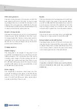
Page 6: ...circuit multi circuit protection valve function When the increasing air pressure in the braking system reaches a preset value cut out pressure the unloader valve signals the purge valve to open and t...

Page 7: ...om the desiccant bed passes through the timing choke and charges the integral timing reservoir During the Purge phase the loss of pressure in the inlet cavity will close the delivery check valve Some...

Page 8: ...n first and in a reasonable time circuits 21 and 22 have a bypass feature Series charging This configuration is designed so that at least one of the circuits 21 and 22 will open before circuits 23 and...

Page 9: ...70 C Silencer D Oil separator Oil separator complete Oil separator seals E Purge valve For standard applications For low temperature applications 45 C F High pressure tyre inflator H Double pressure s...

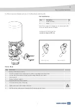
Page 10: ...er clockwise using suitable strap wrench 2 Remove O ring 2 3 Wipe the body with a clean rag Protect the clean air chamber and cartridge mounting thread from dirt Fitting the cartridge 1 Lightly lubric...

Page 11: ...pond to that shown on separate Service Kit leaflets Step Service task Removal of the heater assembly 1 Clean the outside of the air processing unit and the surroundings of the heater area 2 Unscrew el...

Page 12: ...silencer assembly 1 over its spigot on the base of the air processing unit 2 Lightly tap the silencer assembly 1 in the direction of the spigot so that it snaps into place 3 Check the fixation of new...

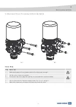
Page 13: ...le please refer to the safety checks on page 4 2 Vent the system air pressure completely 3 Disconnect air lines after noting which port they are connected to for correct reinstallation 4 Unscrew and r...

Page 14: ...x 2 5 mm 1 3 t O ring 42 x 2 5 mm 1 4 t Screw M 4 x 40 mm 2 5 t O ring 33 x 5 mm 1 6 Desiccant cartridge 1 Part Identification and Service Kits 3 2 1 5 6 For Service Kit Part Number see www knorr brem...

Page 15: ...urn using a suitable strap wrench 10 Refit if necessary the air processing unit to vehicle and check according to chapter 3 10 11 Charge the air system to just below cut out pressure and check the des...

Page 16: ...ommended pulling tool for Oil Separator Unit disassembly Components of pulling tool Correct fitting of pulling tool Dimensions of thrust plate Dimensions of pulling tool legs Holder with threaded bolt...

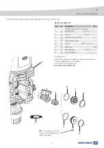
Page 17: ...ty 1 Air Processing Unit APU housing 1 2 Retaining ring 27 2 x 1 2 1 3 O ring 24 x 1 5 1 4 Exhaust piston assembly 1 5 Compression spring 1 6 O ring 25 12 x 1 78 1 7 End cover 3 or 2 8 Retaining ring...

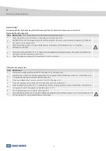
Page 18: ...it retaining ring 8 or 2 securely into groove of the APU housing unit 1 using suitable tool e g circlip pliers Fitting the new purge valve Step Service task Read and understand all steps before commen...

Page 19: ...the new threaded connector 5 5 Fit the new metallic sealing ring 3 to the threaded connector 5 and screw in 6 Tighten the threaded connector 5 to a torque of 50 Nm 7 Check operation by pushing valve...

Page 20: ...ce against the O rings 1 until the new screws 2 are fitted and fully tightened to a torque of 6 Nm 3 Refit if necessary the air processing unit to vehicle and check according to chapter 3 10 4 Prior t...

Page 21: ...in a way to prevent movement but allowing for easy access to the required part 3 Remove the four screws 6 while holding the cover 5 against the compression spring see Fig 1 4 Remove the cover 5 and O...

Page 22: ...2 into APU housing 1 don t touch or move the K ring see Fig 8 8 If the K ring moves out of alignment from concentric position start again from Step 4 9 Place compression spring 3 onto piston 2 see Fi...

Page 23: ...See above table for recommended tightening torques 4 Charge the air system to cut out pressure 5 Check all fittings and seals for leakage using soap and water There should be no leakage 6 Deplete the...

Page 24: ...4698 USA Bendix CommercialVehicle Systems LLC Elyria OH Tel 1 440 329 9100 Fax 1 440 329 9105 Asia Australia Australia Knorr Bremse Australia Pty Ltd Granville NSW Tel 61 2 8863 6500 Fax 61 2 8863 651...

Reviews: