background image

36

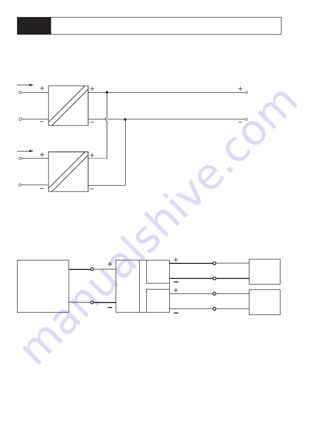
3) Séparation des potentiels avec ajout de courant à des courants continus

4) Câblage du diviseur de signaux normalisés

Entrée

Sortie IS

ProLine P2240x P1

IS


= IE1 + IE2

IE1

Entrée

IE2

ProLine P22412 P1

Entrée

Sortie 1

Sortie 2

Transmetteur

Afficheur

API, SCP

UE = US1 + US2 – 5,8 V

Exemples de câblage

Summary of Contents for ProLine P224 P1 Series

Page 1: ... The Art of Measuring www knick de Aktuelle Produktinformation Stratos Pro A2 PH Betriebsanleitung Aktuelle Produktinformation www knick de SE 706X 1 NMSN 14163 Berlin BVS 10 ATEX E089 X II 1G Ex ia IIC T3 T4 T SE 706X 2 NMSN 14163 Berlin BVS 10 ATEX E089 X II 1G Ex ia IIC T3 T4 T6 BVS 10 ATEX E089 X II 1G Ex ia IIC T3 T4 T6 SE 706X 1 NM 14163 Berlin BVS 10 ATEX E II 1G Ex ia IIC SE 706X 2 NM 1416...

Page 2: ...rtificate GL Approval DNV GL Type Test Certificate Declaration of Conformity for ATEX Zone 2 Equipment Functional Safety Type Approved TÜV SIL3 Functional Safety Certificate The documents listed above are available for download at www knick de ...

Page 3: ...ung 5 Garantie 5 Lieferprogramm 5 Entsorgung 5 Beschaltungsbeispiele 7 Anschlussbelegung 9 Maßzeichnung 10 Technische Daten 11 SIL Sicherheitshandbuch 13 Geltungsbereich 13 Ermittelte sicherheitstechnische Kennwerte 14 Installation und Inbetriebnahme 16 Wiederholungsprüfung 16 Wartung 16 Reparatur 16 ...

Page 4: ... Gerät integriert wird liegt in der Verantwortung des Errichters des Systems Installation Der Normsignaltrenner darf nur von qualifiziertem Fachpersonal installiert werden Die 20 mA Signalleitungen dürfen bei SIL Anwendungen keine galvanische Verbindung zum Netz haben Die nationalen Vorschriften müssen bei der Installation und Auswahl der Zuleitungen be achtet werden Achten Sie auf eine geeignete ...

Page 5: ...ne P22401 P1 Normsignaltrenner ohne Hilfsenergie 1 kanalig P22401P1 ProLine P22402 P1 Normsignaltrenner ohne Hilfsenergie 2 kanalig P22402P1 ProLine P22412 P1 Normsignal Splitter ohne Hilfsenergie P22412P1 Schutz gegen Verpolung Bei Verpolung am Ein oder Ausgang und einem zu hohen Strom löst eine selbst rückstellende Sicherung PTC aus und begrenzt den Strom Wenn die Verpolung be seitigt wird erhol...

Page 6: ...6 Prinzipschaltbild P2240x P1 Strom eingang Z 32 V C 1 0 µF Strom ausgang Z 32 V C 1 0 µF 6 Ω Kurzbeschreibung UE UA 2 9 V 2 5 Ω selbstrückstellende PTC Sicherung ...

Page 7: ...g werden vertauscht angeschlossen speisende SPS SPS Ausgang UA ProLine P2240x P1 2 Leiter Transmitter UA UE 2 9 V Eingang UE Ausgang UA ProLine P2240x P1 2 Leiter Transmitter UE UA 2 9 V SPS 4 Leiter Transmitter Eingang Ausgang ProLine P2240x P1 z B SPS PLS etc Kanal 1 Kanal 2 z B C bar etc 0 4 20 mA 0 4 20 mA 0 4 20 mA 0 4 20 mA z B C bar etc Beschaltungsbeispiele Speisung Eingang UE ...

Page 8: ...bei eingeprägten Strömen 4 Beschaltung des Normsignal Splitters Eingang Ausgang IA ProLine P2240x P1 IA IE1 IE2 IE1 Eingang IE2 ProLine P22412 P1 Eingang Ausgang 1 Ausgang 2 Transmitter Anzeiger SPS PLS UE UA1 UA2 5 8 V Beschaltungsbeispiele ...

Page 9: ...senergie 2 kanalig P22412 P1 Normsignal Splitter ohne Hilfsenergie 2 1 CH2 Out Out2 2 2 CH2 Out Out2 3 1 Out CH1 Out Out1 3 2 Out CH1 Out Out1 4 1 In CH1 In In 4 2 In CH1 In In 5 1 CH2 In 5 2 CH2 In Anschluss über steckbare Schraubklemmen 3 2 2 2 5 1 4 1 3 1 2 1 5 2 4 2 3 2 4 1 3 1 4 2 Anschlussbelegung ...

Page 10: ...10 114 5 mm 111 5 mm 12 5 mm 112 5 mm 99 0 mm Maßzeichnung ...

Page 11: ... v M je 100 Ω Bürde Referenztemp 23 C Übertragungsverhalten Speisetrennerbetrieb Übertragungsfehler 0 08 v E Zusatzfehler 0 08 v E 10 V Eingangsspannung Temperatureinfluss1 TK 40 ppm K v M 10 V Eingangsspannung Referenztemp 23 C Isolation Prüfspannung Eingang gegen Ausgang 5 4 kV AC 50 Hz Kanäle untereinander 3 6 kV AC 50 Hz Arbeitsspannung Schutz gegen gefährliche Körperströme Bis 600 V AC DC sic...

Page 12: ...K im spezifizierten Betriebs Temperaturbereich 2 Die 20 mA Signalleitungen dürfen bei SIL Anwendungen keine galvanische Verbindung zum Netz haben 3 Mean Time Between Failures gemäß EN 61709 SN 29500 Voraussetzungen in gepflegten Räumen mittlere Umgebungstemperatur 40 C keine Belüftung Dauerbetrieb 4 Geschlossene Bereiche wettergeschützt Wasser und windgetriebener Niederschlag Regen Schnee Hagel us...

Page 13: ...nn in sicherheitsrelevanten Anwendungen bis SIL 3 einge setzt werden systematische Eignung Die für den Einsatzzweck relevanten Normen wie z B EN 61508 EN 61511 EN 62061 und EN ISO 13849 sind anzuwenden Sicherheitsfunktion Der Normsignaltrenner überträgt ein Messsignal von 4 bis 20 mA galvanisch getrennt in ein Ausgangssignal von 4 bis 20 mA Die Übertragung der Eingangssignale erfolgt dabei linear ...

Page 14: ...rkannter gefährlicher Ausfälle SFF 98 6 Anteil ungefährlicher Ausfälle DC 0 keine Diagnose 2 MTTFD 221 Jahre3 Mittlere Betriebsdauer bis zum gefährlichen Ausfall KAT 1 1oo1 bzw 3 1oo2 Kategorie gemäß EN 13849 1 PL c 1oo1 bzw e 1oo2 Performance Level gemäß EN 13849 1 SIL 3 Sicherheits Integritäts Level gemäß EN 61508 MTTR 72 h max Reparaturzeit Austausch eines defekten Geräts durch ein Ersatzgerät ...

Page 15: ...sch eines defekten Geräts durch ein Ersatzgerät gleichen Typs Temperatur max 40 C Mittlere Temperatur über einen langen Zeitraum PFH PFD Werte T1 1 a T1 2 a T1 3 a PFD1oo1 4 x 10 5 4 7 9 x 10 5 7 9 1 2 x 10 4 11 9 PFH1oo1 1 h 9 x 10 9 9 9 x 10 9 9 9 x 10 9 9 PFD1oo2 4 x 10 7 0 4 7 9 x 10 6 0 79 1 2 x 10 6 1 2 PFH1oo2 1 h 9 x 10 10 0 9 9 x 10 10 0 9 9 x 10 10 0 9 T1 Prüfintervall zwischen Funktions...

Page 16: ... Funktion der Sicherheitsfunktion im Zusammenwirken aller Komponenten nachgewiesen wird Überprüfung der Funktion Die dokumentierten PFD Werte gelten für die Prüfintervalle T1 1 2 oder 3 Jahre Die Funktionsfähigkeit des Normsignaltrenners ist in der Anwendung zu prüfen Dabei ist wie folgt zu verfahren Sollwerte für Messbereichsanfang und ende sowie eines Mittelwertes z B 50 Wert vorgeben Es ist zu ...

Page 17: ...nst Polarity Reversal 19 Warranty 19 Product Range 19 Disposal 19 Wiring Examples 21 Connection Assignment 23 Dimension Drawing 24 Specifications 25 SIL Safety Manual 27 Scope 27 Determined Safety Characteristics 28 Installation and Commissioning 30 Proof Test 30 Maintenance 30 Repair 30 ...

Page 18: ...s responsible for the safety of the system in which the device is integrated Installation Only trained and qualified personnel should install the P224xx P1 loop powered isolator For SIL applications the 20 mA signal lines must be galvanically isolated from the mains Be sure to observe the national codes and regulations during installation and selection of cables and lines Make sure that the connec...

Page 19: ...tor for standard signals 1 channel P22401P1 ProLine P22402 P1 Loop powered isolator for standard signals 2 channels P22402P1 ProLine P22412 P1 Loop powered splitter for standard signals P22412P1 Protection against Polarity Reversal When input or output polarity are reversed and the current is too high a resettable fuse PTC trips and breaks the circuit When polarity reversal is corrected the fuse w...

Page 20: ...20 Block Diagram P2240x P1 Current input Z 32 V C 1 0 µF Current output Z 32 V C 1 0 µF 6 Ω Short Description Vin Vout 2 9 V 2 5 Ω resettable PTC fuse ...

Page 21: ...s Input and output are connected in reverse feeding PLC PLC Output Vout ProLine P2240x P1 2 wire transmitter Vout Vin 2 9 V Input Vin 4 wire transmitter Input Output ProLine P2240x P1 eg PLC PCS etc Channel 1 Channel 2 eg C bar etc 0 4 20 mA 0 4 20 mA 0 4 20 mA 0 4 20 mA eg C bar etc Wiring Examples Output Vout ProLine P2240x P1 2 wire transmitter Vin Vout 2 9 V PLC Power supply Input Vin ...

Page 22: ...dition for Impressed Currents 4 Wiring of Standard Signal Splitter Input Output Iout ProLine P2240x P1 Iout Iin1 Iin2 Iin1 Input Iin2 ProLine P22412 P1 Input Output 1 Output 2 Transmitter Indicator PLC PCS Vin Vout1 Vout2 5 8 V Wiring Examples ...

Page 23: ...rd signals 2 channels P22412 P1 Loop powered splitter for standard signals 2 1 CH2 Out Out2 2 2 CH2 Out Out2 3 1 Out CH1 Out Out1 3 2 Out CH1 Out Out1 4 1 In CH1 In In 4 2 In CH1 In In 5 1 CH2 In 5 2 CH2 In Connections via Pluggable Screw Terminals 3 2 2 2 5 1 4 1 3 1 2 1 5 2 4 2 3 2 4 1 3 1 4 2 Connection Assignment ...

Page 24: ...24 114 5 mm 111 5 mm 12 5 mm 112 5 mm 99 0 mm Dimension Drawing ...

Page 25: ...3 C Transmission behavior for operation as repeater power supply Transmission error 0 08 full scale Additional error 0 08 full scale 10 V input voltage Temperature influence1 Tc 40 ppm K meas val 10 V input voltage reference temp 23 C Isolation Test voltage Input against output 5 4 kV AC 50 Hz Channels against one another 3 6 kV AC 50 Hz Working voltage protection against electric shock Up to 600 ...

Page 26: ... Average Tc in specified operating temperature range 2 For SIL applications the 20 mA signal lines must be galvanically isolated from the mains 3 Mean Time Between Failures according to EN 61709 SN 29500 Conditions operation in well kept rooms average ambient temperature 40 C no ventilation continuous operation 4 Closed weather protected operating areas water or wind driven precipitation rain snow...

Page 27: ... The loop powered isolator can be used in safety related applications up to SIL 3 systematic suitability The standards relevant for the application shall be applied for example EN 61508 EN 61511 EN 62061 and EN ISO 13849 Safety Functions The loop powered isolator transmits a 4 to 20 mA measurement signal galvanically isolated to the output The input signals are transmitted linearly at a ratio of 1...

Page 28: ...ted failures SFF 98 6 Fraction of non hazardous failures DC 0 no diagnostics 2 MTTFD 221 years3 Mean operating time until dangerous failure CAT 1 1oo1 or 3 1oo2 Category according to EN 13849 1 PL c 1oo1 or e 1oo2 Performance level according to EN 13849 1 SIL 3 Safety integrity level according to EN 61508 MTTR 72 h max time to repair Replacing a defective device by a replace ment device of the sam...

Page 29: ...8 MTTR 72 h max time to repair Replacing a defective device by a replace ment device of the same model Temperature Max 40 C Long time average temperature PFH PFD Values T1 1 a T1 2 a T1 3 a PFD1oo1 4 x 10 5 4 7 9 x 10 5 7 9 1 2 x 10 4 11 9 PFH1oo1 1 h 9 x 10 9 9 9 x 10 9 9 9 x 10 9 9 PFD1oo2 4 x 10 7 0 4 7 9 x 10 6 0 79 1 2 x 10 6 1 2 PFH1oo2 1 h 9 x 10 10 0 9 9 x 10 10 0 9 9 x 10 10 0 9 T1 Time i...

Page 30: ... the flawless operation of the safety functions in conjunction with all components Checking the Function The documented PFD values apply to the test intervals T1 1 2 or 3 years The correct functioning of the loop powered isolator must be checked in the application Proceed as follows Adjust values for start and end of range and an average value e g 50 value Check if the measurement error lies withi...

Page 31: ... Garantie 33 Gamme de produits 33 Elimination et récupération 33 Exemples de câblage 35 Correspondance des bornes 37 Dessin coté 38 Caractéristiques techniques 39 Guide de sécurité SIL 41 Champ d application 41 Caractéristiques de sécurité déterminées 42 Installation et mise en service 44 Contre essai 44 Entretien 44 Réparation 44 ...

Page 32: ... est intégré l appareil relève de la responsabilité de l instal lateur dudit système Installation Le séparateur de signaux normalisés P224xx P1 ne doit être installé que par un personnel qualifié Dans le cas d applications SIL les câble de signaux 20 mA ne doivent pas avoir de liaison galvanique avec le secteur Les règlements nationaux doivent être respectés lors de l installation et de la sélecti...

Page 33: ...ans alimentation 1 canal P22401P1 ProLine P22402 P1 Séparateur de signaux normalisés sans alimentation 2 canaux P22402P1 ProLine P22412 P1 Diviseur de signaux normalisés sans alimentation P22412P1 Protection contre l inversion de polarité En cas d inversion de polarité à l entrée ou à la sortie avec un courant trop élevé un fusible réarmable PTC se déclenche et limite le courant Dès lors que le pr...

Page 34: ...34 Schéma de principe P2240x P1 Entrée de courant Z 32 V C 1 0 µF Sortie de courant Z 32 V C 1 0 µF 6 Ω Description succincte UE US 2 9 V 2 5 Ω Fusible réarmable PTC ...

Page 35: ... et la sortie sont connectées de façon inversée API d alimentation API Sortie US ProLine P2240x P1 Transmetteur à 2 fils US UE 2 9 V Entrée UE Transmetteur à 4 fils Entrée Sortie ProLine P2240x P1 par ex API SCP etc Canal 1 Canal 2 par ex C bar etc 0 4 20 mA 0 4 20 mA 0 4 20 mA 0 4 20 mA par ex C bar etc Exemples de câblage Sortie US ProLine P2240x P1 Transmetteur à 2 fils UE US 2 9 V API Alimenta...

Page 36: ...courant à des courants continus 4 Câblage du diviseur de signaux normalisés Entrée Sortie IS ProLine P2240x P1 IS IE1 IE2 IE1 Entrée IE2 ProLine P22412 P1 Entrée Sortie 1 Sortie 2 Transmetteur Afficheur API SCP UE US1 US2 5 8 V Exemples de câblage ...

Page 37: ...ignaux normalisés sans alimen tation 2 canaux P22412 P1 Diviseur de signaux normalisés sans alimen tation 2 1 CH2 Out Out2 2 2 CH2 Out Out2 3 1 Out CH1 Out Out1 3 2 Out CH1 Out Out1 4 1 In CH1 In In 4 2 In CH1 In In 5 1 CH2 In 5 2 CH2 In Raccordement par bornes à vis enfichables Correspondance des bornes ...

Page 38: ...38 Dessin coté 114 5 mm 111 5 mm 12 5 mm 112 5 mm 99 0 mm ...

Page 39: ...e charge temp de réf 23 C Caractéristique de transmission en mode séparateur d alimentation Erreur de transmission 0 08 d f Erreur supplémentaire 0 08 d f 10 V tension d entrée Influence de la température1 Tc 40 ppm K de val mes 10 V tension d entrée temp de réf 23 C Isolation Tension d essai Entrée sortie 5 4 kV CA 50 Hz Canaux entre eux 3 6 kV CA 50 Hz Tension de service protection contre les ch...

Page 40: ...de température spécifiée 2 Dans le cas d applications SIL les câbles de signaux 20 mA ne doivent pas avoir de liaison galvanique avec le secteur 3 Mean Time Between Failures selon EN 61709 SN 29500 Conditions préalables température ambiante moyenne 40 C pas d aération fonctionnement continu 4 Lieux fermés utilisation fixe sur site à l abri des intempéries eau et précipitations portées par le vent ...

Page 41: ...bles Le séparateur de signaux normalisés peut être utilisé dans des applications liées à la sécurité jusqu à SIL 3 adéquation systématique Les normes relatives aux diffé rentes applications sont à prendre en compte par ex EN 61508 EN 61511 EN 62061 und EN ISO 13849 Fonction de sécurité Le séparateur de signaux normalisés transmet un signal de mesure de 4 à 20 mA à isolation galvanique à la sortie ...

Page 42: ...D 0 FIT Taux de défaillances dangereuses détectées SFF 98 6 Part de défaillances non dangereuses DC 0 pas de diagnostic 2 MTTFD 221 ans3 Durée de fonctionnement moyenne avant défaillance dangereuse CAT 1 1oo1 ou 3 1oo2 Catégorie selon EN 13849 1 PL c 1oo1 ou e 1oo2 Niveau de performance selon EN 13849 1 SIL 3 Niveau de sécurité intégrée selon EN 61508 MTTR Temps de réparation 72 h max Remplacement...

Page 43: ...cement d un appareil défectueux par un appareil de même type Température max 40 C Température moyenne sur une longue durée Valeurs PFH PFD T1 1 a T1 2 a T1 3 a PFD1oo1 4 x 10 5 4 7 9 x 10 5 7 9 1 2 x 10 4 11 9 PFH1oo1 1 h 9 x 10 9 9 9 x 10 9 9 9 x 10 9 9 PFD1oo2 4 x 10 7 0 4 7 9 x 10 6 0 79 1 2 x 10 6 1 2 PFH1oo2 1 h 9 x 10 10 0 9 9 x 10 10 0 9 9 x 10 10 0 9 T1 Intervalle de contrôle entre les ess...

Page 44: ...n de sécurité en interaction avec tous les composants Vérification du fonctionnement Les valeurs PFD documentées s appliquent à l intervalle de contrôle T1 1 2 ou 3 ans Le bon fonctionnement du séparateur de signaux normalisés doit être vérifié dans l application Pour cela procéder comme suit Spécifier des valeurs de consigne pour la fin de la plage de mesure ainsi qu une valeur moyenne par ex val...

Page 45: ...e 47 Garantia 47 Linha de Produtos 47 Descarte 47 Exemplos de Fiação 49 Arranjo de Terminais 51 Desenho Dimensional 52 Especificações 53 Manual de Segurança SIL 55 Escopo 55 Determinação das Características de Segurança 56 Instalação e Comissionamento 58 Teste 58 Manutenção 58 Reparo 58 ...

Page 46: ...istema ao qual o instrumento for integrado Instalação O isolador P224xx P1 só deverá ser instalado por técnicos qualificados e treinados Para aplicações com níveis de segurança SIL as linhas de sinal de 20 mA precisam ser isola das galvanicamente da rede elétrica Não deixe de observar as leis e regulamentos vigentes durante a instalação e a seleção de cabos e dutos Certifique se de que os cabos te...

Page 47: ...la malha para sinais convencionais 1 canal P22401P1 ProLine P22402 P1 Isolador alimentado pela malha para sinais convencionais 2 canais P22402P1 ProLine P22412 P1 Divisor alimentado pela malha para sinais convencionais P22412P1 Proteção Contra Inversão de Polaridade Quando a polaridade da entrada ou saída são invertidas e a corrente fica alta demais um fusível PTC interrompe o circuito Quando a in...

Page 48: ...48 Diagrama de Blocos P2240x P1 Entrada de corrente Z 32 V C 1 0 µF Saída de corrente Z 32 V C 1 0 µF 6 Ω Sinopse Vin Vout 2 9 V 2 5 Ω fusível PTC recuperável ...

Page 49: ... entrada e a saída são conectadas invertidas CLP alimentador CLP Saída Vout ProLine P2240x P1 Transmissor a 2 fios Vout Vin 2 9 V Entrada Vin Transmissor a 4 fios Entrada Saída ProLine P2240x P1 p ex CLP SCP etc Canal 1 Canal 2 p ex C bar etc 0 4 20 mA 0 4 20 mA 0 4 20 mA 0 4 20 mA p ex C bar etc Exemplos de Fiação Saída Vout ProLine P2240x P1 Transmissor a 2 fios Vin Vout 2 9 V CLP Alimentação En...

Page 50: ...nte para Correntes Impressas 4 Divisão de Sinal Convencional Entrada Saída Iout ProLine P2240x P1 Iout Iin1 Iin2 Iin1 Entrada Iin2 ProLine P22412 P1 Entrada Saída 1 Saída 2 Transmissor Indicador CLP SCP Vin Vout1 Vout2 5 8 V Exemplos de Fiação ...

Page 51: ...ntado pela malha 2 canais P22412 P1 Divisor de sinais con vencionais alimen tado pela malha 2 1 CH2 Out Out2 2 2 CH2 Out Out2 3 1 Out CH1 Out Out1 3 2 Out CH1 Out Out1 4 1 In CH1 In In 4 2 In CH1 In In 5 1 CH2 In 5 2 CH2 In Conexões via Terminais Roscados Plugáveis 3 2 2 2 5 1 4 1 3 1 2 1 5 2 4 2 3 2 4 1 3 1 4 2 Arranjo de Terminais ...

Page 52: ...52 114 5 mm 111 5 mm 12 5 mm 112 5 mm 99 0 mm Desenho Dimensional ...

Page 53: ... carga de 100 Ω temperatura de referência 23 C Comportamento de transmissão para operação como fonte de alimentação repetidora Erro de transmissão 0 08 no fim de escala Erro adicional 0 08 no fim de escala tensão da entrada 10 V Influência da temperatura1 Tc 40 ppm K do valor medido tensão da entrada 10 V temperatura de referência 23 C Isolação Tensão de teste Entre entrada e saída 5 4 kVca 50 Hz ...

Page 54: ...a 2 Para aplicações com níveis de segurança SIL as linhas de sinal de 20 mA precisam ser isoladas galvanicamente da rede elétrica 3 Tempo Médio Entre Falhas MTBF conforme norma EN 61709 SN 29500 Condições operação em ambientes bem conservados temperatura ambiente média 40 ºC sem ventilação operação contínua 4 Área fechada e protegida contra água e precipitações chuva neve granizo etc 5 Pressão do ...

Page 55: ...isoladores podem ser usados em aplicações com segurança até SIL 3 adequa bilidade do sistema As normas pertinentes deverão ser aplicadas por exemplo EN 61508 EN 61511 EN 62061 e EN ISO 13849 Funções de Segurança Os isoladores transmitem um sinal de medição de 4 a 20 mA com isolação galvânica entre entrada e saída Os sinais de entrada são transmitidos linearmente na razão de 1 1 O sinal de erro é d...

Page 56: ...lhas perigosas detectadas SFF 98 6 Fração de falhas sem risco DC 0 sem diagnósticos 2 MTTFD 221 anos3 Tempo médio de operação até ocorrer falha perigosa CAT 1 1oo1 ou 3 1oo2 Categoria conforme norma EN 13849 1 PL c 1oo1 ou e 1oo2 Nível de desempenho conf EN 13849 1 SIL 3 Nível de integridade de segurança conforme norma EN 61508 MTTR Tempo p reparo 72 h máx Substituição de um instrumento defeituoso...

Page 57: ...508 MTTR Prazo para reparo 72 h máx Substituição de um instrumento defeituoso por outro novo do mesmo modelo Temperatura 40 C máx Temperatura média a longo prazo Valores de PFH PFD T1 1 a T1 2 a T1 3 a PFD1oo1 4 x 10 5 4 7 9 x 10 5 7 9 1 2 x 10 4 11 9 PFH1oo1 1 h 9 x 10 9 9 9 x 10 9 9 9 x 10 9 9 PFD1oo2 4 x 10 7 0 4 7 9 x 10 6 0 79 1 2 x 10 6 1 2 PFH1oo2 1 h 9 x 10 10 0 9 9 x 10 10 0 9 9 x 10 10 0...

Page 58: ...ção sem falhas das funções de segurança juntamente com todos os componentes Checagem da Função Os valores FDP documentados aplicam se ao intervalo de teste T1 1 2 ou 3 anos É preciso verificar se o isolador está funcionando corretamente na aplicação Proceda como segue Ajuste os valores de início e fim de faixa e um valor médio p ex 50 Veja se o erro de medição se encontra dentro das tolerâncias es...

Page 59: ...EX ...

Page 60: ...090580 TA 254 220 KNX03 20151218 Knick Elektronische Messgeräte GmbH Co KG Beuckestraße 22 14163 Berlin Tel 49 30 80191 0 Fax 49 30 80191 200 www knick international com knick knick de ...

Reviews: