


8
Setup of the HPLC pump K-120
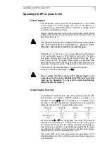
Rear view of the HPLC pump K-120
Rear panel
1
2
3
4
5
6
Fig. 3
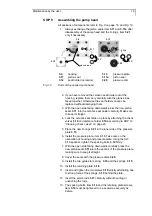
Rear view of the HPLC pump K-120
1
Fan
2
RS-232 serial interface
3
Remote
control
connection
4
Serial
number
5
Power
supply
6
Ground
connection
The power supply
5
and an additional ground connection
6
are
there located as well as a RS-232 serial interface
2
for external
computer control and remote control input and output
3
:
START IN:
connection for START/STOP as short circuit (or TTL-low)
against ground
ERROR OUT:
output for error signals (open collector) against ground
GROUND:
ground connection for start and error signals
Bottom elements
1
2
3
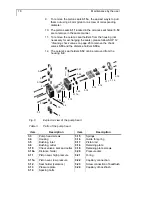
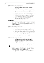
Fig. 4
Bottom elements
1
DIP-switch 1 for START IN remote control logic’s
2
DIP-switch 2 for START/STOP logic’s
3
trim potentiometer screw for safety switch off


