


SECTION 3
OPERATION
p. 3-2
05146410
●
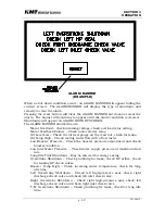
Overstroke
(no longer called Leak)
shutdown level is adjustable
between 30% and 120% of full capacity. The overstroke warning
level is automatically set 10% below the shutdown level set by the
operator. Overstroke warnings, pending shutdowns and shutdowns
are issued in three types, left, right and intensifier. An intensifier
warning or shutdown indicates that the intensifier is shifting too fast
in both directions and would point more towards a problem with the
orifice or plumbing rather than check valves or seals. If a left or
right shutdown occurs, the display tells the operator which parts are
suspect. Sometimes, especially if the intensifier is running near full
capacity an intensifier shutdown can be displayed when it is actually
caused by a left or right fault. This can be diagnosed further by
turning the operating pressure down and watching the
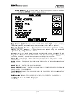
Alarms
screen, which displays all alarm occurrences.
●
Real-time running capacity and stroke rate are shown on the
display.
●
A resettable stroke counter for both intensifier one and intensifier
two are provided on the display.
●
The part numbers for both the PLC and display logic along with the
software revision number running on the machine are shown on the
Maintenance Screen.
●
The PLC monitors the motor overload relay and displays a message
when the overloads trip. The overloads will now be set on automatic
reset rather than manual so the enclosure does not have to be
opened to reset them.
●
The display will give a message (
motor feedback failure
) if the start
relay does not close at start-up or opens due to fault.
●
The start-up sequence will depend on the circumstances.
(
1) Standard machine-start up after machine has been E-
stopped:
Safety dump valve will be open. It will close 3 seconds
after the intensifier begins stroking. The pump will be held in
low pressure for 20 seconds after motor is started after which
pressure will go to high if high is selected, otherwise will stay in
low.
The purpose for this is to allow entrapped air to be bled from any
HP cylinder that has been maintained to avoid hot air burning
the plunger seals.
(2) Standard machine-start up after normal stop:
Safety dump
valve will be closed, pump will be held in low pressure for 20
seconds after motor is started, after which the pressure will go to
high if high is selected, otherwise will stay in low. The purpose
for this is to allow entrapped air to be bled from any HP cylinder
that has been maintained to avoid hot air burning the plunger
seals.
Summary of Contents for STREAMLINE SL-IV 50 PLUS
Page 54: ...SECTION 4 MAINTENANCE Page 4 9 49831902 ...
Page 139: ...SECTION 12 PARTS LISTS page 12 5 80079163 ...
Page 141: ...SECTION 12 PARTS LISTS page 12 7 80079163 ...
Page 143: ...SECTION 12 PARTS LISTS page 12 9 80079163 ...
Page 145: ...SECTION 12 PARTS LISTS page 12 11 80079163 ...
Page 147: ...SECTION 12 PARTS LISTS page 12 13 80079163 ...
Page 149: ...SECTION 12 PARTS LISTS page 12 15 80079163 ...
Page 151: ...SECTION 12 PARTS LISTS page 12 17 80079163 ...
Page 153: ...SECTION 12 PARTS LISTS page 12 19 80079163 ...
Page 155: ...SECTION 12 PARTS LISTS page 12 21 80079163 ...
Page 157: ...SECTION 12 PARTS LISTS page 12 23 80079163 ...
Page 159: ...SECTION 12 PARTS LISTS page 12 25 80079163 ...
Page 161: ...SECTION 12 PARTS LISTS page 12 27 80079163 ...
Page 163: ...SECTION 12 PARTS LISTS page 12 29 80079163 ...
Page 165: ...SECTION 12 PARTS LISTS page 12 31 80079163 ...
Page 167: ...SECTION 12 PARTS LISTS page 12 33 80079163 ...
Page 169: ...SECTION 12 PARTS LISTS page 12 35 80079163 ...
Page 171: ...SECTION 12 PARTS LISTS page 12 37 80079163 ...
Page 173: ...SECTION 12 PARTS LISTS page 12 39 80079163 ...
Page 174: ......
Page 175: ......
Page 176: ......
Page 177: ......
Page 178: ......
Page 179: ......