


SECTION 3
OPERATION
p. 3-1
05146410
Section 3 OPERATION
3
SL-IV PUMP OPERATION-
Note: all operational control functions for this KMT Waterjet SL-IV pump
are provided by the motion / cutting table / box OEM. For a description
of the KMT Waterjet model SL-IV pump sensors and solenoids, see
Section 8: ‘Electrical Systems’.
This section is devoted to an explanation of the SL-IV+ control logic and
operators interaction with it. The SL-IV+ has comprehensive fault
detection and troubleshooting logic in the control, and allows operator
control of the sensitivity of the overstroke detection in order to optimize
the logic for specific operating conditions. The operator functions and
warnings programmed in the control of this intensifier offers an
unprecedented and comprehensive view of the operating parameters,
impending faults, shutdown faults, and suggested remedies. The
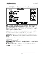
operator’s interface is through a touch sensitive control display on the
control console where several menu screens can be selected for various
purposes. The screens and their use are explained in this section. The
pages following will explain the functions available in the control and
how to select and use them.
Following is an explanation of the functions of the control logic, including
the start-up sequence.
●
The intensifier is equipped with a booster pump output pressure
switch. Seven seconds after the intensifier is started, the switch is
monitored. If the switch opens, a warning is issued (message and
flashing red light). If the condition persists for 30 consecutive
seconds, the intensifier is shut down.
●
The intensifier is equipped with an inlet cutting water pressure
switch. If the switch is not closed, the intensifier will not start and a
warning is issued (message and red flashing light). After the
intensifier is started, if the switch opens, the same warning is issued.
If the condition persists for 20 consecutive seconds, the intensifier is
shut down.
●
The intensifier is equipped with separate total hour and maintenance
hour meters for intensifier one and intensifier two. The operator can
reset both maintenance meters. Both total meters can be set to any
value via a password protected configuration screen. Without access
to this screen, the hour meters can not be reset or changed.
●
The Intensifier is equipped with a maintenance function to allow the
user to set the plunger in either the left or right position for ease of
maintenance.
Summary of Contents for STREAMLINE SL-IV 50 PLUS
Page 54: ...SECTION 4 MAINTENANCE Page 4 9 49831902 ...
Page 139: ...SECTION 12 PARTS LISTS page 12 5 80079163 ...
Page 141: ...SECTION 12 PARTS LISTS page 12 7 80079163 ...
Page 143: ...SECTION 12 PARTS LISTS page 12 9 80079163 ...
Page 145: ...SECTION 12 PARTS LISTS page 12 11 80079163 ...
Page 147: ...SECTION 12 PARTS LISTS page 12 13 80079163 ...
Page 149: ...SECTION 12 PARTS LISTS page 12 15 80079163 ...
Page 151: ...SECTION 12 PARTS LISTS page 12 17 80079163 ...
Page 153: ...SECTION 12 PARTS LISTS page 12 19 80079163 ...
Page 155: ...SECTION 12 PARTS LISTS page 12 21 80079163 ...
Page 157: ...SECTION 12 PARTS LISTS page 12 23 80079163 ...
Page 159: ...SECTION 12 PARTS LISTS page 12 25 80079163 ...
Page 161: ...SECTION 12 PARTS LISTS page 12 27 80079163 ...
Page 163: ...SECTION 12 PARTS LISTS page 12 29 80079163 ...
Page 165: ...SECTION 12 PARTS LISTS page 12 31 80079163 ...
Page 167: ...SECTION 12 PARTS LISTS page 12 33 80079163 ...
Page 169: ...SECTION 12 PARTS LISTS page 12 35 80079163 ...
Page 171: ...SECTION 12 PARTS LISTS page 12 37 80079163 ...
Page 173: ...SECTION 12 PARTS LISTS page 12 39 80079163 ...
Page 174: ......
Page 175: ......
Page 176: ......
Page 177: ......
Page 178: ......
Page 179: ......