


STE-6014/6017/6018/6019/6020 Room Temperature Sensors
2
Installation Guide
STE-6014/6017/6018
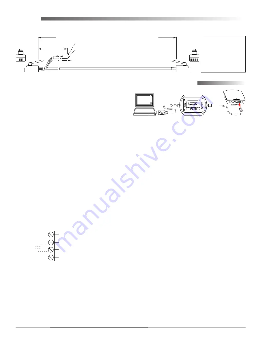
Connecting any of these models to a controller
requires a special cable with (on the sensor end) an
RJ-45 connector and (on the controller end) an RJ-11
connector with an additional three wires (as relevant
to the model) for controller inputs. Purchasing
preassembled cables from KMC is more
cost-
effective
and
reliable
than creating custom cables in
the field. Use one of the following cables:
KMD-569
•
3
= 25 feet
KMD-569
•
4
= 50 feet
KMD-569
•
5
= 75 feet
The three additional wire connections are:
Orange
•
is the
thermistor
input to the controller
Orange/white
•
is the
setpoint
signal input to the
controller
Green
•
is the auxiliary
supply voltage
of 10 VDC
to the STE-6018 LED (for the STE-6014/6017, clip
or tape the unused wire)
KMD–569
3
= 25 feet; KMD–569
4
= 50 feet; KMD–569
5
= 75 feet
1
8
Orange
Wire =
Thermistor
Input to Controller
Orange/White
Wire =
Setpoint
Signal Input to Controller
(for STE-6014/6016/6017/6018 only; clip or tape when not used)
12 inches
5
2
RJ-11 and
Wire Leads
to Controller
RJ-45
to STE
Sensor
Green
Wire = Aux.
Supply Voltage
to STE-6015/6018
(10 VDC) or STE-6016 (7.5/12 VDC) (clip or tape when not used)
RJ-11 RJ-45
Color
(Lead)
8
Orange
7
N.C.
(Lead)
6
Green
3
5
Blue
4
4
Blue/White
5
3
Green/White
2
N.C.
(Lead)
1
Orange/White
(
Cables crossed, 20 AWG
)
Wiring
Connect wires as shown for the relevant model.
STE-6019/6020
Common (Ground)
Thermistor (10k Ohms)
A
B
C
Potentiometer
(Override
Button)
D
10 VDC LED Supply (from Controller;
for STE-6020 Only)
At the bottom of the STE-6014/6017/6018 case is
an EIA-485 (formerly RS-485) computer port. This
port provides a temporary connection to the digital
network for network setup or troubleshooting.
To use the port to connect to a computer, a means of
converting the EIA-485 signal to a USB or EIA-232
(formerly RS-232) signal will be needed. The exact
connection depends on the computer and the opera-
tor workstation software. (See also the instructions
included with those devices and software.)
For
•
USB
(to WinControl or BACstage), use a
KMD-5576 USB Communicator (see the illustra-
tion above).
For
•
EIA-232 to BACstage
, use a third-party
interface.
For
•
EIA-232 to WinControl
, use a KMD-5559
CommTalk and KMD-5624 cable (or equivalent
interface).
To access the network through the STE’s sensor:
1. Connect the keyed, flat end of the KMD-5624
interface cable (included with the KMD-5576 but
not the KMD-5559) to the port on the sensor.
2. Connect the other end of the cable to the interface
device that converts the EIA-485 signal into an
EIA-232 or USB signal.
3. Connect the suitable cable from the interface
device to the computer’s serial or USB port. Install
any required software and configure the port as
necessary.
KMD-5624
Cable
KMD-5576
PC Port Connection


