After all of the outputs discharged, the instrument starts to switch the outputs step by step. The number of a step is displayed in the second line and appropriate output
is switched on for a short time. After the step is switched off, its type and size is displayed :
•
three-phase reactive power of 7.38 kvar, capacitive, in the third line
•
in the second line (behind the output number) type of the capacitor – three-phase type (C123) because of all of three bars displayed behind the step number
If a step power was detected as zero, either the output is not used (nothing connected to it) or the step power is too small to be recognized automatically.
After the process passes, new recognized output data are stored into the instrument's memory.
Then, in case that :
•
at least one valid output ( capacitor or choke ) was found
•
the instrument is not switched into the
manual
mode
•
no alarm action is active
•
voltage and current higher than measurable minimums
the instrument starts to control power factor to preset value.
If the undercurrent (
I<
) alarm ( No. 04, parameter 43 ) was disabled for the AOR-process to be able to pass without any load in the network do not forget to
reenable it back !!!
Detailed AOR process explanation and all of the instrument functions' description can be found at the full-scale operating manual.
2.2.3 PFC Control & PFC Alarms Setup
Finally, the PFC control parameters (1 ÷ 19) and the PFC alarms parameters (40 ÷ 56) can be modified, if necessary.
Detailed description of all of the parameters can be found in the full-scale operating manual.
2.3 Parameter Checking & Editing
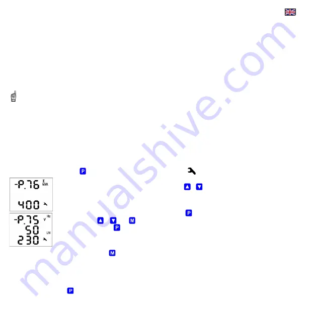
To check or edit the parameters, press the
key. As default, parameter group 01 is displayed and symbol
(wrench) indicates, that setup data are displayed now.
The parameters are arranged in groups, numbered from 00 up. The number of group is displayed in the first line in format
-
P
.
n
n
(with
preceding dash). You can browse through the parameter groups with the
or
keys.
If one parameter only in the group, its value is usually in the bottom line as shown at the example (nominal power 400 kVA).
If two parameters in the group, usually the first of them is displayed in the 2
nd
line and the second in the 3
rd
line ( nominal frequency 50 Hz
and nominal voltage 230 V).
To edit a particular parameter, scroll to its group. Then press and hold the
until the value gets flashing. Now release the key and set
target value with the
or
, or the
key for some of parameters. You can use autorepeat function by keeping one of the arrow keys
pressed too. Finally, press the
and the value is stored into the memory.
If more parameters in the group, the first one is chosen when entering editing mode for the first time. If you want to modify the second
parameter only, simply cancel editing of the first parameter without any change and reenter the editing again – now the second parameter is
chosen.
To return back to measured values display, simply press the
key. Such return can occur automatically too when no manipulation with the buttons for about 30 seconds.
2.3.1 Side Branch Parameters
The parameter groups are organized by ordinal number in the main branch.
The main branch
is identified with a dash
in the 1
st
line
, preceeding the parameter group number –
for example
-
P
2
5
.
Some of the parameter groups (No. 25÷28, alarm parameter groups No. 40÷56, etc.) are located on side branches for easier navigation. You can switch to a side branch with
certain parameters by pressing the
key and switch back to the main branch in the same way. Unlike the main branch, when the side branch is selected the dash is
displayed in the 2nd line.


