


14 of 24
15 of 24
Loosen the screws sufficiently to allow the compound slide to be turned to the desired angle,
as indicated on the scale, and secure the slide in this position by retightening the socket head
screws.
The taper, or bevel, is cut by setting the cross-slide appropriately then using the compound
slide feed handle to advance the cutting tool in the direction of the arrow as shown in Fig. 9.
SCREWCUTTING
This operation requires a degree of skill and accuracy, and should not be attempted unless you
are completely familiar with all aspects of the lathe.
Essentially, the cross-slide (6)will move towards the headstock (1) under power, the same as
cutting using auto feed, except the rate of feed is faster, as determined by the gear
configuration. The cutting tool therefore, is moving ever closer to the rotating chuck.
WARNING:
Great care and concentration must be exercised to ensure that the two do not meet
when the machine is operating, as the possible damage caused could be disastrous.
The lathe is supplied with a leadscrew that will produce Imperial Treads in a range from 12 to 52
threads per inch, or metric threads in a range from 0.4-2.0mm pitch. It is important to remember
that the type of thread you need to cut, i.e. UNF, BA, BSP, BSW etc., will be totally dependent
upon the cutting tool profile, as profiles differ from thread to thread.
For detailed information regarding screwcutting techniques, cutting tools etc., you should
consult a suitable handbook or obtain advice from a qualified person.
The general procedure for screwcutting is as follows:
1. Try to get as much distance from the chuck to the end of the proposed screw thread as
possible, and if your design allows, cut a ‘run-off’ into the workpiece which is of a smaller
diameter than the root diameter of the proposed screw thread.
Note:
for long threads it may be necessary to use a separate ‘steady rest’ (not included).
2. Install the appropriate gears for the thread required, and correctly mount the cutting tool.
3. Set the required depth of cut, and position the tool ready to begin cutting.
Note:
The depth of cut is vitally important and may be calculated or obtained from an
appropriate reference manual.
4. Take all necessary precautions previously stated, and start the lathe with automatic feed
lever (15) in the disengaged position (UP).
5. Push the automatic feed lever down sharply and turn the Forward/Off/Reverse switch (24) to
‘FORWARD’.
6. As the tool approaches the end of the desired thread, turn the Forward/Off/Reverse switch to
‘OFF’ but do not disengage the auto-feed lever.
7. Retract the tool, using the cross-slide feed handle (18), noting the exact position on the scale
and the exact number of turns (this will be used in step 9).
8. Turn the Forward/Off/Reverse switch to ‘REVERSE’. The cross-slide will wind back to the
beginning then turn switch to ‘OFF’.
9. Reset the lathe by winding the cross-slide IN the exact number of turns previously wound
OUT (step 7) then continue to wind IN to the desired depth of cut.
10. Repeat steps 5 – 7 until the thread is completed.
After Each Use
Remove all metal shavings from the lathe and thoroughly clean all surfaces. If coolant was
used, ensure it has completely drained from the tray.
Storage
Store the lathe when it is not in use. Store it in a dry, secure place out of the reach of children.
Inspect the lathe for good working condition prior to storage and again before re-use.
Components should be dry, and all machined surfaces should be lightly oiled. Always remove
cutting tools before storage store them separately.
Put the switch in the locked or off position before storing the lathe. Such preventive safety
measures reduce the risk of starting the lathe accidentally when used next.
Maintenance
WARNING:
• Always disconnect the lathe from power before servicing it. Make sure the switch is in OFF
position before reconnecting.
Maintain the Lathe by adopting a program of conscientious repair and maintenance in
accordance with the following recommended procedures. It is recommended that the general
condition of any tool be examined before it is used. Keep your tool in good repair. Keep all
cutting tools sharp and clean. Properly maintained cutting tools with sharp cutting edges are
less likely to bind and are easier to control. Keep handles dry, clean, and free from oil and
grease. The following chart is based on a normal operation schedule.
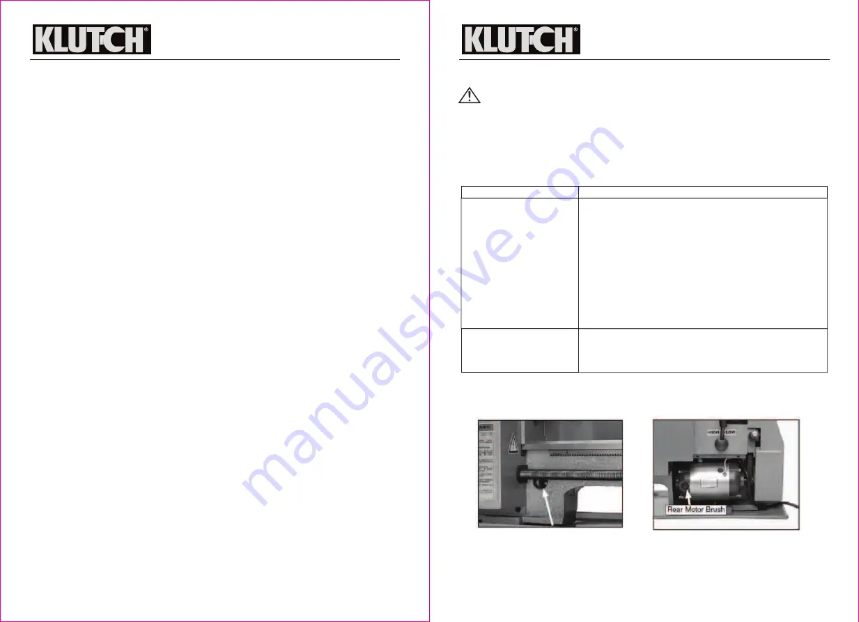
MOTOR BRUSHES
The motor brushes may be changed by unscrewing the caps, on the upper side of the motor,
beneath the headstock..
Mini Metal Lathe 7 x 12
OWNER’S MANUAL
Mini Metal Lathe 7 x 12
OWNER’S MANUAL
USE LUBRICATING OIL
Daily maintenance
Monthly maintenance
Maintenance Point
Check loose mounting bolts.
Check damaged parts.
Check poorly adjusted parts.
Check worn or damaged wires.
Check any other unsafe condition.
Clean tooling and storage.
Cleaning the machine is relatively easy. Remove all chips at
the end of the day. Wipe up any coolant used that settled in
the bottom of the chip tray or has settled on any other part of
the lathe. Dry off entire machine with a clean, dry towel. do
not use compressed air to clean your lathe.
Check gear damage, wear, rust, sludge, or chip build-up
inside gearbox and off motor.
Clean and lube as necessary.