


12 of 24
13 of 24
Mini Metal Lathe 7 x 12
OWNER’S MANUAL
Mini Metal Lathe 7 x 12
OWNER’S MANUAL
Operation
SIMPLE TURNING
Before starting the machine, as described above, it is imperative that the setup for the type of
work to be carried out is fully checked.
The following notes are guidelines as to how to set up the lathe in order to carry out a simple
turning operation.
1. ALWAYS plan your work. Have drawings or a plan on hand together with any measuring
instruments you may require, such as micrometers, calipers, etc.
2. Select a cutting tool that will produce the desired cut and mount it, with as little over-hang as
possible, securing it using three hex socket head screws. (Ideally, the over-hang should be
approx., 6mm but not more than 8mm for a straight tool).
3. It is IMPORTANT to ensure that the tip of the cutting tool is on the center line of the work, or
very slightly below it. The tip should never be above the center line.
Where necessary shims should be used beneath the tool in order to achieve the correct height,
or, if the tip is too high, the only recourse is to select another tool or grind down the tip.
To check that the tip is at the correct height, position the tool so that the tip is almost touching
the point of the tailstock center. They should coincide. lf necessary make adjustments using
shims grind down the cutting tip or select another tool.
4. When satisfied, mount the work, either in the chuck or on a faceplate, and if necessary, use
the tailstock (9) center for additional support (if the work cannot be adequately secured by
the chuck, or if it is a long piece, or of small diameter). Additionally, a ‘steady rest’ may be
used.
If the tailstock will not be used, you may remove it completely by loosening off the securing nut
at its base, and sliding it free of the bed.
5. Mark the surface of the work at the point where the cut is to end, i.e. the shoulder, using a
scriber or similar means, and move the cross-slide (6) so that the cutting tool is directly
opposite the mark, then wind in the cross-slide so that the tool touches the surface of the
work.
6. While carrying out these maneuvers, rotate the chuck
by hand to ensure that nothing will come into contact
with it when turning takes place, i.e. there is adequate
clearance between the cross-slide, tool post, or
cutting tool, and the chuck.
7. When satisfied, retract the cutting tool and wind the
cross-slide (6)away from the headstock (1), then wind
the cutting tool up to the work, somewhere along the
length to be cut, whilst rotating the work by hand,
using the chuck.
Continue to advance the cutting tool slowly, until it just touches the surface. Record this
position by zeroing the scale on the cross-slide, i.e. turn the moveable scale until the tool is a
short distance from the right hand edge of the work. Wind in the cross-slide again one full
until the zero marks again coincide.
IMPORTANT:
If you go past the zero mark, back off again at least one half of a turn, then
slowly bring the marks back together.
Whenever you use the scale as an indicator, to advance the cross-slide or compound slide,
ALWAYS use this procedure to align the marks. This is to take into account backlash and
other clearances in the gearing, slides, etc.
8. Continue to turn the handle (18) an amount equivalent to your desired depth of cut.
NOTE:
We recommend that for rough cutting, you do not exceed 0.010"(0.25mm) as your
depth of cut.
9. The setup is now complete to begin your cutting operation, but before starting, check that
the position of the Clutch (24) is Off.
10. Switch the machine on and slowly feed the cutting tool into the work using the manual feed
handle. Proceed until you reach the previously marked line on the work, and then retract the
tool one or two complete turns on the Cross-slide feed handle (16).
11. Wind the cross-slide back to the beginning then wind the tool the same number of turns
“in”, plus the depth of desired cut, and proceed to cut once more.
NOTE:
This procedure describes general, rough cutting. For other types of cuts-finishing,
cutting shoulders etc., consult a suitable handbook.
SIMPLE TURNING WITH POWER FEED
Simple turning with power feed has the same basic setup is used as described above, except
that, before starting, the Leadscrew F/N/R lever (27) is set to the ‘Forward’ position and the
Automatic feed lever (15) is operated in order to drive the cross-slide.
As mentioned previously, the rotational speed of the leadscrew, and hence the rate of feed of
the tool, is dependent upon the gear configuration of the gear train.
• The feed rate for simple turning is considerably less than that used for screw cutting.
• The lathe is factory configured for simple turning, however if you have been screw cutting,
always remember to reset the gear configuration to that for simple turning.
• Please refer to the chart on a previous page that shows the gear configuration, and the
explanation of how to change the gears.
1. Taking all precautions previously mentioned, position the cutting tool a short distance to the
right of the workpiece with the appropriate depth of cut set on the cross-slide.
2. Ensure the leadscrew F/N/R lever (27) is set to ‘Forward’ and select ‘Forward’ on the
Forward/Off/Reverse switch (24) on the main control panel.
3. Switch on the lathe.
4. Turn the variable speed control knob (23) to achieve the desired spindle speed with your right
hand and push down on the automatic feed lever (15) until the nut becomes firmly engaged
with the leadscrew.
IMPORTANT: Your left hand should always be free in order to hit the emergency stop (25)
should it become necessary.
5. Carefully observe the movement of the tool and as it approaches the mark on the surface,
denoting the end of cut, pull the automatic feed lever (15) UP sharply and ensure it stays UP.
If a degree of accuracy is required, it is recommended that you finish the cut by hand.
NOTE: If you require a shoulder with perfectly clean corners, then you need to use an
appropriately shaped tool.
6. Retract the tool one or two complete turns on the cross-slide feed (6), then wind it so that the
tool is at the start point once again. Advance the tool the same number of turns, plus the
depth of cut, and when read, push down the automatic feed lever (15) and proceed to take
another cut.
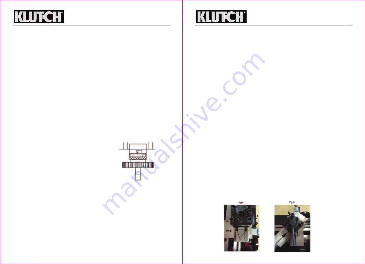
BEVEL CUTTING
Bevel cutting involves the use of the compound slide (7), which is mounted on the cross-slide
(6) and set at right angles to it for all normal cutting operations. This is indicated by the zero
mark, on the scale, (B, Fig. 8), lining up with the mark etched on the body of the cross-slide.
To set the compound slide so that the cutting tool will cut a bevel, first retract the slide, until the
two hex, socket head screws (A) are revealed as shown in Fig. 9.