Multiplexer
10 Control Settings for the DIGITAL I/O interface
A8
KLIPPEL Analyzer System
Page 9 of 16
Power supply connection with removed earth contact could cause high voltages at the enclosure of the device.
Never operate the device under condensing conditions!
Control Settings for the DIGITAL I/O interface
The mapping of the hardware control input pins to the internal 4 bit control register can be selected by the
customer. There is a dip switch for each control bit on the backside of the device
.
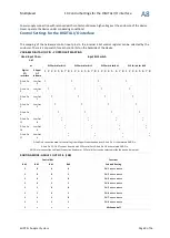
VARIABLE DIGITAL I/O PIN – CONTROL BIT MAPPING
Used Input Chan-
nel
Input Bit Switch
at
DIP Switch for Bit 3
DIP Switch for Bit 2
DIP Switch for Bit 1
DIP Switch for Bit 0
Digital
I/O
Interface
Klippel
QC
Software
1 2 3 4 5 6 7 8 1 2 3 4 5 6 7 8 1 2 3 4 5 6 7 8 1 2 3 4 5 6 7 8
D-Sub Pin
2
User Out
9
O
N
O
N
O
N
O
N
D-Sub Pin
3
User Out
7
O
N
O
N
O
N
O
N
D-Sub Pin
4
User Out
5
O
N
O
N
O
N
O
N
D-Sub Pin
5
User Out
3
O
N
O
N
O
N
O
N
D-Sub Pin
6
O
N
O
N
O
N
O
N
D-Sub Pin
15
User Out
8
O
N
O
N
O
N
O
N
D-Sub Pin
16
User Out
6
O
N
O
N
O
N
O
N
D-Sub Pin
17
User Out
4
O
N
O
N
O
N
O
N
D-Sub Pin 6 cannot be used for controlling from
Klippel Production Analyzer
, D-Sub Pin 1 is the related GND Pin.
D-Sub Pin 15, 16, 17 cannot be used with
PC Parallel Port
, D-Sub Pin 18 is the related GND Pin
GND Pin for connection to
Klippel Production Analyzer
or
PC Parallel Port
can be selected inside the device via jumper.
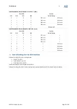
ROUTING MODE: SINGLE 1 OUT OF 8 (1X8)
Control Bits
Functions
Bit 3
Bit 2
Bit 1
Bit 0
Selected Routing
0
0
0
0
CH 1
to BUS A & BUS B
0
0
0
1
CH 2
to BUS A & BUS B
0
0
1
0
CH 3
to BUS A & BUS B
0
0
1
1
CH 4
to BUS A & BUS B
0
1
0
0
CH 5
to BUS A & BUS B
0
1
0
1
CH 6
to BUS A & BUS B
0
1
1
0
CH 7
to BUS A & BUS B
0
1
1
1
CH 8
to BUS A & BUS B
1
x
x
x
All channels off

