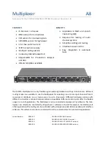
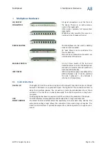
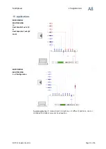
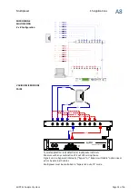
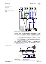

Multiplexer
1
A8
KLIPPEL Analyzer System
Page 11 of 16
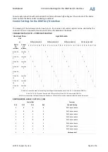
Control Settings for the Direct Control Interface
Control Settings for DIRECT CONTROL interface (high active)
MUX Control Input
Function (Selected Routing)
D-Sub Pin 1
CH 1
to BUS A
& CH 1
to BUS B -
if Pin 9 is at high level
D-Sub Pin 2
CH 2
to BUS A
& CH 2
to BUS B -
if Pin 9 is at high level
D-Sub Pin 3
CH 3
to BUS A
& CH 3
to BUS B -
if Pin 9 is at high level
D-Sub Pin 4
CH 4
to BUS A
& CH 4
to BUS B -
if Pin 9 is at high level
D-Sub Pin 5
CH 5
to BUS B
& CH 5
to BUS A -
if Pin 9 is at high level
D-Sub Pin 6
CH 6
to BUS B
& CH 6
to BUS A -
if Pin 9 is at high level
D-Sub Pin 7
CH 7
to BUS B
& CH 7
to BUS A -
if Pin 9 is at high level
D-Sub Pin 8
CH 8
to BUS B
& CH 8
to BUS A -
if Pin 9 is at high level
D-Sub Pin 9
1 out of 8 mode
(connects BUS A and BUS B)
D-Sub Pin 10
Bypass
from Channel
1
to
5
(only used if Option Bypass Switchable is installed additional)
D-Sub Pin 11
Bypass
from Channel
2
to
6
(only used if Option Bypass Switchable is installed additional)
D-Sub Pin 12
Bypass
from Channel
3
to
7
(only used if Option Bypass Switchable is installed additional)
D-Sub Pin 13
Bypass
from Channel
4
to
8
(only used if Option Bypass Switchable is installed additional)
D-Sub Pin 14
IEPE
Mic Supply for Channel
1
to
4
(only for the BNC multiplexer)
D-Sub Pin 15
IEPE
Mic Supply for Channel
5
to
8
(only for the BNC multiplexer)
D-Sub Pin 16
Direct Control ON (must be high for Direct Control interface operation)
D-Sub Pin 17 and 35
alternative supply voltage input 12 to 24 V
DC
(only if external power supply is not used)
D-Sub Pin 18 and 36
supply GND (if external power supply is not used, could be connected to D-Sub Pin 19 & 37)
D-Sub Pin 19 and 37
related GND for D-Sub Pins 1 to16 (must be connected for correct operation)
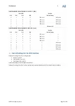
Control Settings for Option Bypass or Bypass Switchable
CONTROL SETTINGS FOR DIGITAL I/O AND USB INTERFACE
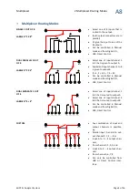
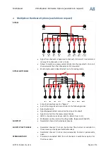
Routing mode: Dual Parallel 1 out of 4 (2 x 4)
Control Bits
Functions
Bit 3
Bit 2
Bit 1
Bit 0
Selected Routing
Bypass switchable
0
0
0
0
1
to BUS A
5
to BUS B
open
0
0
0
1
2
to BUS A
6
to BUS B
open
0
0
1
0
3
to BUS A
7
to BUS B
open
0
0
1
1
4
to BUS A
8
to BUS B
open
1
0
x
x
All channels off
open
0
1
0
0
1
to BUS A
5
to BUS B
closed: 2
to
6, 3
to
7, 4
to
8
0
1
0
1
2
to BUS A
6
to BUS B
closed: 1
to
5, 3
to
7, 4
to
8
0
1
1
0
3
to BUS A
7
to BUS B
closed: 1
to
5, 2
to
6, 4
to
8
0
1
1
1
4
to BUS A
8
to BUS B
closed: 1
to
5, 2
to
6, 3
to
7
1
1
x
x
All channels off
closed: 1
-
5, 2
-
6, 3
-
7, 4
-
8
option Bypass (if installed) behaves as Bit 2 is permanently set