


User's Manual
LINE 212-6 / LINE 212-9
KLING & FREITAG GMBH ©2003 - 2005
Version 4.1, 23.03.2006
Page 22 of 37
10.
Wiring
The Speaker is equipped with two parallel-wired Speakon connectors.
Before connecting your Line 212 system as shown in chapter 10.3 , be sure to switch
off all connected appliances and turn down all level controls.
−
We recommend the use of high-quality cables provided by KLING & FREITAG.
−
For connections to the power amplifier inputs, please use 2-pin shielded microphone
cable with high-quality connectors.
−
Avoid ground loops (see chapter 10.2 )
−
Please pay attention to the respective pin diagrams in this manual!
−
To ensure an in-phase operation and, consequently, a homogeneous sound, make
sure that the +/- polarity of the speakers at the amplifier is correct.
−
When simultaneously using power amplifiers from different manufacturers, be sure to
use the correct specific pin configuration. It may be necessary to modify the pin con-
figuration on the power amplifiers or on the connectors leading to them.
−
To avoid loss of power, the cables should have a minimum wire gauge of 2.5 mm² -
more for longer cabled distances. A minimum wire gauge can be easily calculated
with the following formula:
If several loudspeakers are connected, the signal can be linked through from one loud-
speaker to the next. Please make sure that the total impedance of the loudspeakers R (W)
is not lower than the minimal impedance indicated on the power amplifier.
1/R
1
+ 1/R
2
+ 1/R
3
+ ... = 1/R
total
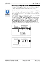
10.1
Connecting the Speakon Plugs to the Connecting Terminal
2.
1.
3.
1.
2.
Important
Minimum wire gauge (mm²) = required cable length (m)
2 x speaker’s impedance (
Ω
)