


SE3KLE1AU_ara_en_c_600_O.doc – 15.02.08
Seite 14 von 47
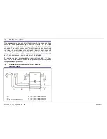
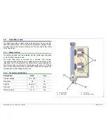
4.4 Flow
sensor
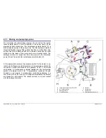
The flow sensor is integrated in the water supply and registers the
amount of incoming water.
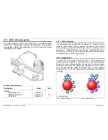
It consists of a housing, a fan impeller with a permanent magnet and
a printed circuit board with reed switch.
The water sets the fan impeller moving. The magnet attached to the
fan impeller actuates a reed switch 2x per revolution (north/south-
south/north).
The generated impulses are counted by the electronics module and
cannot be measured.
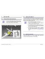
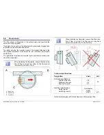
When installing the flowmeter, ensure that the direc-
tion of flow is correct. An arrow on the flow sensor
indicates the direction of flow.
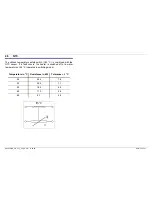
When installing the flowmeter, ensure that the direc-
tion of flow is correct. The flow sensor may have
a maximum incline of 30° to the left only.
Technical specifications:
Designation Value
Unit
Hydraulic specifications:
Minimum flow rate
Maximum flow rate
Nominal flow rate
0.8
4.0
2.5
l/m
Electrical specifications
Output signal:
Switching
current:
Rectangular
signal
max. 5
mA
Nominal output signal at 2.5 l/min flow rate: 208 impulses / litre
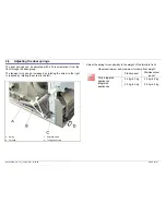
A Water
inlet
B Water
outlet
C Connector


