background image

Operating Instructions KLAROconnect 


Status 06/2022 

KLARO GmbH  

  Page 4/21 

IMPORTANT:  


These operating instructions contain information on the installation of electrical com-
ponents and must therefore be read before mounting and commissioning the set! 


All safety instructions must be observed! 


Keep for future use. 


About these operating instructions 

1

These operating instructions are part of the product and must be read 

before the unit is put into 

operation. 

The operating instructions must be kept for the entire service life of the system and must 

be available for reference. 

1.1  Original language of the documentary 

This documentation was originally written in German. 

1.2  Copyright 

© KLARO GmbH 

Spitzwegstrasse 63 

D-95447 Bayreuth 


Phone: 0049-921-16279120 


E-mail: [email protected] 

Internet: 

www.klaro.eu


All rights expressly reserved. Reproduction or communication to third parties, in whatever form, is not 

permitted without the written consent of KLARO GmbH. 

1.3  Completeness 

These instructions have been prepared with due care. Any liability of the manufacturer due to incorrect 

or missing information as well as linguistic deficiencies or typographical errors in the documentation is 

excluded. Should you find any incompleteness and/or errors, please inform us at the above address. 

In preparing these instructions, care was taken to ensure that the facts stated therein correspond as 

closely as possible to the associated system. Nevertheless, all technical data, dimensions and illustra-

tions in these instructions are non-binding. Possible claims regarding the specific design of a system 

cannot be derived from them. 

We reserve the right to make changes to a system within the scope of improvements and further de-

velopments without changing these instructions. An obligation to install modified technology in already 

completed and delivered systems cannot be derived from this. 

This documentation is updated regularly. 

1.4  Responsibility 

Any responsibility of the manufacturer does not apply: 

  non-observance or insufficient use of the information in this manual, 

  Use of spare parts or parts on the system that have not been approved by KLARO GmbH, 

  Removal, manipulation or bypassing of protective devices, 

  unauthorised changes to the system, 

  improper execution of maintenance and replacement of spare parts. 


Unauthorised modifications to the system or operation of the system outside the specifications provid-

ed by the manufacturer will invalidate any warranty claims. 


Summary of Contents for 970716

Page 1: ...GERMAN DESIGN AND ENGINEERING KLAROconnect Operating manual 317 EN 0622 Direct access to the plant data Operational safety for the wastewater treatment plant 4G LAN We provide clear water...

Page 2: ...Operating Instructions KLAROconnect Status 06 2022 KLARO GmbH Page 2 21 Original operating instructions Communication module KLAROcon nect...

Page 3: ...ESCRIPTION 10 5 5 1 ELECTRICAL INTERFACES 10 5 1 1 Power supply and serial interface X6 10 5 1 2 USB 2 0 11 5 1 3 LAN Ethernet connection 11 5 1 4 SMA antenna connection 11 5 2 OPERATING ELEMENTS 12 5...

Page 4: ...s or typographical errors in the documentation is excluded Should you find any incompleteness and or errors please inform us at the above address In preparing these instructions care was taken to ensu...

Page 5: ...https klaro webmonitor de Via KLARO connect all operation relevant data such as settings events and operating hour meter readings of the KLAROcontrol S and KLAROcontrol M are transmitted to the KLARO...

Page 6: ...STK Data cable 901474 1 STK LTE indoor antenna 901476 1 STK LTE outdoor antenna 980194 10 CM Velcro tape 901475 1 STK Ethernet extension cable 980314 1 STK Cable gland M16 980311 1 STK Locknut M16 Inc...

Page 7: ...KLAROconnect is used to mount the communication module Note The glued areas must be made dust free before applying the Velcro tape 3 3 2 Mounting adapter available from WAGO The KLAROconnect can be mo...

Page 8: ...ons KLAROconnect Status 06 2022 KLARO GmbH Page 8 21 Basic connection diagram 1 Control unit KLAROcontrol M or KLAROcontrol S 2 KLAROconnect communication module 3 Antenna 4 Data cable serial cable po...

Page 9: ...n KLAROconnect After the card has been inserted KLAROconnect can be connected to the power supply switch on KLAROcontrol The connection with KLAROcontrol is fully automatic A WEB symbol appears in the...

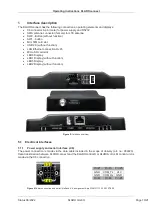
Page 10: ...cro SD card slot LED6 Display LED1 Display without function LED5 Display LED2 Display without function Figure 5 Interface overview 5 1 Electrical interfaces 5 1 1 Power supply and serial interface X6...

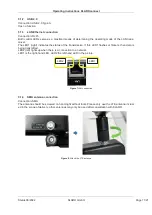
Page 11: ...atus of the transmission If this LED1 flashes or flickers then data is being transmitted LED2 left lights up when there is a connection to a network LED1 is the right hand LED LED2 the left hand LED i...

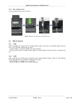
Page 12: ...d for mini SIM Figure 10Insert the mini SIM card into the KLAROconnect Removing and inserting the SIM card during operation requires initialisation of the KLAROconnect software Therefore the KLAROconn...

Page 13: ...are the switching states ON and OFF In the ON state LED6 lights up green Interval 100ms on 100ms on 800ms off normal function In the event of a reset or similar the LED lights up continuously for a fe...

Page 14: ...enu can also be called up alternatively via the assigned IP in the DHCP server of the router 6 2 SIM profile configuration A SIM card profile with details of the APN of the provider can be created via...

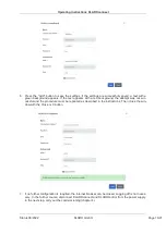
Page 15: ...y on the screen press the F5 key Then create a new profile with the Add button 4 A new window Mobile broadband opens The connection name can be freely assigned The fields Connection name and APN must...

Page 16: ...th a red background the attempt was not suc cessful and the procedure must be repeated as described in the instructions Then close the win dow with the Close or X button 7 If no further configuration...

Page 17: ...on is established Responses from the KLAROcontrol are passed on to the WebMonitor via the KLAROconnect using the websocket ws 6 3 1 Websocket URI Configuration Guide 1 Call up the KLAROconnect menu vi...

Page 18: ...o the power supply 5 Firmware is automatically installed from the micro SD card The process takes approx 7 to 10 minutes 6 After the process is completed KLAROconnect switches off automatically Green...

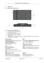
Page 19: ...B41 WCDMA B1 B2 B4 B5 B6 B8 B19 GSM B2 B3 B5 B8 Voice Speech Codec Modes HR FR EFR AMR AMR WB Echo Arithmeti c Echo Cancellati on Noise Suppression Audio Digital Audio and VoLTE Voice over LTE Opti o...

Page 20: ...dBm 10 MHz LTE B8 99 8 dBm 10 MHz LTE B12 99 8 dBm 10 MHz LTE B13 99 5 dBm 10 MHz LTE B18 100 dBm 10 MHz LTE B19 99 9 dBm 10 MHz LTE B20 99 8 dBm 10 MHz LTE B25 100 dBm 10 MHz LTE B26 99 5 dBm 10 MHz...

Page 21: ...joint approx 137 00 mm without tilt joint Diameter approx 19 60 mm tip approx 21 60 mm max approx 13 50 mm SMA 8 4 LTE outdoor antenna Specification LTE Band 1 10 12 20 23 25 30 33 41 44 Frequency ra...

Page 22: ...plate Type plate contains information on product designation type item number art no serial number in writing and bar code SN power supply U software version SW hardware version HW The MAC address is...

Page 23: ......

Page 24: ...ill Kedrinski rangizzz KLARO GmbH Bayreuth 2022 KLARO GmbH klaro_gmbh KLARO GmbH E Mail Adresse info klaro eu Message Further information under www klaro eu Internet Technical hotline 49 0 921 16279 3...

Reviews: