background image

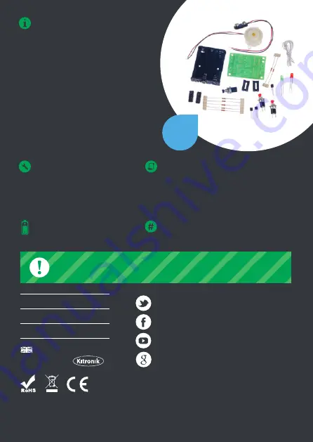
Two people (or two teams) can used the 
quiz buzzer to show who pressed their 
button first. When the button is pressed 
the buzzer sounds and either the red or 
green light is illuminated to show who 
was fastest. This project is brilliant for 
learning about a wide range of 
electronic parts.

For more information on RoHS and CE please visit kitronik.co.uk/rohs-ce. Children 

assembling this product should be supervised by a competent adult. The product contains 

small parts so should be kept out of reach of children under 3 years old.

WARNING

Contents may inspire creativity

0845 8380781

T:

www.kitronik.co.uk

W:

[email protected]

E:

TOOLS REQUIRED:

- Soldering Iron

- Solder

- Wire Cutters

- Wire Strippers

KIT REQUIRES 

3 x AA Batteries

STOCK CODE

2116 or 1016 (Retail Version)

INSTRUCTIONS:

This booklet contains build instructions 

and a circuit explanation. For more 

detailed resources please visit our 

website www.kitronik.co.uk/2116

Designed & manufactured
in the UK by

Kit of

parts

kitronik.co.uk/twitter

kitronik.co.uk/facebook
kitronik.co.uk/youtube
kitronik.co.uk/google

Summary of Contents for QUIZ BUZZER KIT

Page 1: ...QUIZ BUZZER KIT WHO ANSWERED FIRST FIND OUT WITH THIS ...

Page 2: ... PCB Ref R1 R2 R3 R5 R7 R4 R6 Value 10K 220Ω Colour Bands Brown black orange Red red brown SOLDER THE IC HOLDERS Solder the two Integrated Circuit IC holders into U1 and U2 When putting them into the board be sure to get them the right way around The notch on the IC holders should line up with the notch on the lines marked on the PCB 2 SOLDER THE TRANSISTOR Solder the transistor into the board whe...

Page 3: ...ow you must attach the battery clip Start by feeding the leads through the strain relief hole near U2 The wire should be fed in from the rear of the board 7 SOLDER THE LEDs Solder the two Light Emitting Diodes into LED1 and LED2 The red LED should go in LED1 and the green LED in LED2 The LEDs won t work if they don t go in the right way around If you look carefully one side of the LED has a flat e...

Page 4: ...he other switch but this time connect them to the PCB where it is marked SW2 8 ATTACH THE RESET SWITCH Attach the reset switch this has a black button First cut and strip two short lengths of the wire supplied Solder one to each of the two terminals on the switch Then solder the other end to the PCB where it is marked reset It does not matter which way around the two wires go 9 INSERT THE IC INTO ...

Page 5: ... board instead ADDING AN ON OFF SWITCH Solder one end of the battery clip to the PCB either black to or red to 1 Solder the other end of the battery clip to the on off switch 2 Using a piece of wire solder the remaining terminal on the on off switch to the remaining power connection on the PCB 3 ...

Page 6: ...yristors match the outline on the PCB The notch on IC holders ICs and PCBs all match The flat edge of each of the LEDs matches the outline on the PCB The colour bands on R4 and R6 are red red and brown The red wire on battery clip goes to Power and the black to power The red wire on buzzer goes to Buzzer and the black to Buzzer The switch with the black button is connected to Reset Check the botto...

Page 7: ...the switch input high both inputs to the AND gate will be high and therefore the output will go high This causes the gate of thyristor Q3 to go high This turns it on allowing electricity to flow through it turning on LED1 As a result of this the anode of the thyristor will be at a low voltage This thyristor stays latched even if the switch is released As the anode of the thyristor is connected to ...

Page 8: ... adult The product contains small parts so should be kept out of reach of children under 3 years old WARNING Contentsmayinspirecreativity 08458380781 T www kitronik co uk W support kitronik co uk E TOOLS REQUIRED Soldering Iron Solder Wire Cutters Wire Strippers KIT REQUIRES 3 x AA Batteries STOCK CODE 2116 or 1016 Retail Version INSTRUCTIONS This booklet contains build instructions and a circuit ...

Reviews: