background image

— 

30 

— 


WLL (t) 

Fig. 

No. 

Part No. 

Part name 

No. 

per 

hoist 

2.5 

5 7.5 10 15 20 


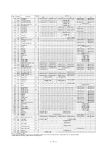
1001 

Top hook set 

C3BA025-1001 

――――――――――――――――――――――――――――――――――――――――――


1071 

Hook latch assembly 

C1FA020-1071 

――――――――――――――――――――――――――――――――――――――――――


Suspender for TSP005 

―――――――――――――――――――――――――――――――――――――――――――――――――――


Suspender for TSG010 

―――――――――――――――――――――――――――――――――――――――――――――――――――


* Suspender 

T5GC025-9004 

――――――――――――――――――――――――――――――――――――――――――


163 

Top pin 

C3BA025-9163 


198 

Split pin  

J1PW01-030025 


1021 

Bottom hook set 

1  C3BA025-1021 

――――――――――――――――――――――――――――――――――――――――――


1071 

Hook latch assembly 

C1FA020-1071 

――――――――――――――――――――――――――――――――――――――――――


41 

Chain pin 

1  C3BA025-9041 

――――――――――――――――――――――――――――――――――――――――――


49 

Slotted nut 

1  C3BA020-9049 

――――――――――――――――――――――――――――――――――――――――――


   10 

96 

Split pin  

1  J1PW01-020014

――――――――――――――――――――――――――――――――――――――――――


11  5101 (1) 

Side plate A assembly 

C3BA025-5101 


12 

806 

Name plate F 

C3BA005-9806 


13  5102 (1) 

Side plate B assembly 

C3BA025-5102 

   14 

116 

Load sheave 

C3BA025-9116 

   15 

140 

Ball bearing 

J1GR002-06007 

   16 

145 

Ball bearing 

J1GR002-06007 

   17  111 (1) 

Pinion 

C3BA025-9111 


 18  130  Roller 

bearing 

C3BA020-9130 

   19 

118 

Snap ring 

C3BA020-9118 

   20 

161 

Guide roller 

C3BA025-9161 

   21 

162 

Stripper 

C3BA025-9162 

   22 

176 

Anchorage 

C3BA025-9176 

―――――――――――――――――――――――


   23 

177 

Stopper pin 

C3BA025-9177 

―――――――――――――――――――――――


   24 

196 

Splint pin 

J1PW01-025018 

―――――――――――――――――――――――


   25 

114 

Load gear  

C3BA025-9114 

   26 

117 

Snap ring 

J1SS000-00032 


C3BA025-5122 


27  5112 (1) 

Gear #2 assembly 

(3) 

   28 

135 

Ball bearing 

J1GR002-06201 


29 

6103 

Gear case assembly 

C3BA025-6103 


30 

800 (1) 

Name plate B with rivets 

C3BG025-9800 

――――――――――――――――――――――――――――――――――――――――――


   31 

181 

Nut 

J1NA001-20120 

   32 

186 

Spring washer 

J1WS011-20120 


33 

179 

Pawl spring (A & B) (2)   

C3BA005-5179 

   34 

155 

Pawl 

C3BA005-9155 

   35 

157 

Snap ring 

J1SS000-00010 


36 

153 (1) 

Friction disc 

C3BA020-9153 


37 

151 (1) 

Friction plate 

C3BA020-9151 


38 

152 (1) 

Ratchet disc 

C3BA005-9152 

   39  154 (1) 

Bushing 

C3BA020-9154 


40 

115 (1) 

Hand wheel 

C3BA025-9115 

   41 

159 

Wheel stopper 

C1FA015-9159 

   42 

167 

Wheel stopper pin 

C3BA005-9167 

   43 

199 

Split pin 

J1PW01-020008 

    44 

5171 

Wheel cover assembly 

C3BA025-5171 

   45 

182 

Nut 

J1NA001-20080 

   46 

187 

Spring washer 

J1WS011-20080 

   47 

841 

Load chain 

1  K7UN080-00000

――――――――――――――――――――――――――――――――――――――――――


   48 

842 

Hand chain 

1  K7NA050-00000

――――――――――――――――――――――――――――――――――――――――――


   49 

931 

Warning tag 

ER1BS9686 

――――――――――――――――――――――――――――――――――――――――――


50 

45 

Chain stopper link 

L5BA032-9045 

――――――――――――――――――――――――――――――――――――――――――


   51 

164 

End pin 

―――――――――――――――――――――――

 C3BA100-9164 

   52 

197 

Split pin 

―――――――――――――――――――――――

 J1PW01-025018 

   53 

176 

Cross guide 

―――――――――――――――――――――――

 C3BA100-9176 

   115 

158 

Washer 

C3BG005-9158 

Notes: * See trolley part lists. 

(1) When ordering replacement part, use the symbol M3B in place of M3 for 2.5t, 5t and larger types, because there are no interchangeability. 
(2) Pawl spring A and B must be used as a set. 
(3) Each number in "WLL" columns is No. per hoist. 

Remark:  Every part quantity becomes twice of the number in the column "parts per hoist" for 20t hoist. 


Summary of Contents for CB005

Page 1: ...9409 10MCE OWNER S OPERATOR S MANUAL AND SAFETY INSTRUCTIONS FOR KITO MANUAL CHAIN HOIST M3SERIES ALWAYS SAVE THIS BOOK FOR FUTURE REFERENCE Original Instruction Issued January 2010 Revised August 20...

Page 2: ...e of hoist operation 7 6 2 Safety working environment 7 6 3 Operation 7 6 4 Hoist storage 7 6 5 Optional overload limiter 8 7 INSPECTION 9 7 1 Outline 9 7 2 Daily inspection 9 7 3 Periodic inspection...

Page 3: ...re injury The safety factor of the lever hoist is 4 1 The hoist may lift and hold a load more than the rated load check that the structure for mounting the chain hoist has sufficient strength Fix the...

Page 4: ...n please contact KITO Corporation or your authorized KITO dealer 4 2 Safety instructions 4 2 1 Before use ALWAYS be sure to wear the proper clothing and personal protective equipment when using and op...

Page 5: ...ance engineers ALWAYS when inspecting and repairing be sure to indicate INSPECTION and carry out without lifting a load NEVER operate a hoist unless the load is centered under the hoist NEVER use the...

Page 6: ...the manufacturer or your dealer if you plan to use a hoist in an excessively corrosive environment saltwater sea air and or acid explosive environment or other corrosive compounds etc NEVER use a hoi...

Page 7: ...5 5 MAIN SPECIFICATIONS 0 5 to 2 5 t 3 to 5 t 7 5 t 10 t 20 t...

Page 8: ...ad 1m This device was tested on the required static and dynamic test provided the European standard EN13157 Dimensions Code WLL t Min distance between hooks C mm a mm b mm d mm e mm f mm g mm h mm k m...

Page 9: ...ot to be caught in a chain idle sheave or other moving parts 1 Face the hand chain wheel side of the hoist 2 To raise the load pull hand chain clockwise 3 To lower the load pull hand chain countercloc...

Page 10: ...hanism which is concentrically equipped on pinion shaft between hand chain wheel and mechanical brake Fig 5 2 Overload limiter Note When the overload limiter operates the maximum load to the product i...

Page 11: ...er condition Replace the latch or hook 3 Hook Check visually The openings of the top and bottom hooks shall not be too wide Replace the hook Check visually No wear deformation or damage Replace the ho...

Page 12: ...urchase with slide calipers No deformation comparing with original shape at time of purchase Replace the hook Check visually Twist shall not be large enough to detect visually Replace the hook 2 Wear...

Page 13: ...of five chain links and check that the maximum length does not exceed value shown in table below Replace the chain 2 Rust flaw deformation Check visually No obvious rust Apply oil as necessary Remove...

Page 14: ...hanism Overhaul and check 1 Flaw on brake surface 37 38 39 Check visually No flaw due to scratching or gouging by foreign matter Replace the part 2 Flaw on friction disc 36 Check visually No flaw due...

Page 15: ...atchet disc 38 Check visually The tooth wear shall not be more than1 5 mm Replace the part Check visually No rust Replace the part Lifting system 1 Wear and deformation of load sheave 14 Check visuall...

Page 16: ...Deformation of top pin hole Check visually Hole shall not be oval Replace the part 2 Slack stay bolt restraint Tap No slack is permitted Replace the side plate Miscellaneous 1 Deformation of stripper...

Page 17: ...o not drag or throw the chain hoist when carrying Never apply oil to the braking part Wipe off dust and moisture and apply oil to the neck of hook and the load chain Storage When not in use ensure tha...

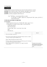
Page 18: ...to 32 To disassemble or reassemble the hoist prepare for the following tools External snap ring plier Internal snap ring plier Wrenches 10mm 12mm 13mm 14mm 17mm 19mm Pliers Plastic hammer Overhaul pro...

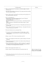
Page 19: ...the top hook 1 from the side plate A 11 and B 13 12 Put a hoist with gear case side or name plate side up 13 Unscrew three nuts 31 with the spring washers 32 fixing the gear case 29 remove the gear c...

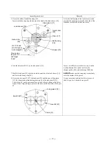
Page 20: ...ed 2 Put the side plate A 11 with a brake cover side down and insert the ball bearing 15 with a snap ring side up into the side plate A Grease the balls of ball bearing shown in the side plate A 3 Ins...

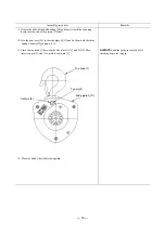
Page 21: ...load sheave 14 and fix it with a snap ring 26 ALWAYS make sure the snap ring is completely set at the bottom of the groove 8 Grease the two gear 2 27 the load gear 25 and the gear of the pinion 17 Pu...

Page 22: ...case 29 to the side plate B 13 and fix them with the three spring washers 32 and nuts 31 11 Place the top hook 1 between the side plate A 11 and B 13 Then insert top pin 4 and fix it with the split p...

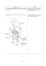
Page 23: ...he load sheave Pull it out between the right guide roller no load side and the load sheave For 10t or larger types pass the no load end of the chain through the cross guide 53 It is recommended for th...

Page 24: ...r 10t and smaller types Connect the no load end of the load chain 47 to end pin 51 which is to be inserted from gear case 29 side Use a split pin 52 to secure the end pin Fix stoppers 114 to the ninth...

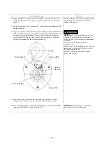
Page 25: ...sc Make sure that the pawl meshes with the ratchet disc properly NEVER apply oil since the brake is dry type Wipe out thoroughly any oil and dirt on the brake The gear of the ratchet disc should point...

Page 26: ...te A 11 and fix them with the spring washers 45 and the nuts 46 22 Insert the other end of the load chain 47 to the bottom hook 6 and fix them with the chain pin 8 slotted nut 9 and split pin 10 ALWAY...

Page 27: ...ing Unless maintenance is performed regularly greased parts will dry resulting in wear and damage and improper meshing of gears Disassemble and replace the pinion gear 2 load gear gear case slide plat...

Page 28: ...TO s sole liability and purchaser s exclusive remedy under this warranty KITO shall not be responsible for any other claims arising out of the purchase and use of KITO s Products regardless of whether...

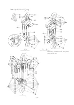
Page 29: ...27 11 PARTS LIST When ordering replacement parts please specify WLL Fig No part No part name and quantity...

Page 30: ...28 Additional parts for 3t and larger types The Chain pin of 10t model is located on top yoke to connect the Load chain 71 2 to 15t 3t 5t 20t...

Page 31: ...015 9177 C3BA020 9177 24 196 Splint pin 1 J1PW01 020012 J1PW01 025015 25 114 Load gear 1 C3BA005 9114 C3BA010 9114 C3BA015 9114 C3BA020 9114 26 117 Snap ring 1 J1SS000 00022 J1SS000 00028 C3BA005 5122...

Page 32: ...1GR002 06201 29 6103 Gear case assembly 1 C3BA025 6103 30 800 1 Name plate B with rivets 1 C3BG025 9800 31 181 Nut 3 J1NA001 20120 32 186 Spring washer 3 J1WS011 20120 33 179 Pawl spring A B 2 2 C3BA0...

Page 33: ...ssembly 3 1 1 1 1 3 3 81 1052 Idle sheave assembly 2 C3BA100 1052 5053 Shaft assembly 1 C3BA030 5053 C3BA050 5053 C3BA050 5053 82 5054 Bottom shaft assembly 1 C3BA100 5054 83 2031 Bottom yoke 2 C3BA03...

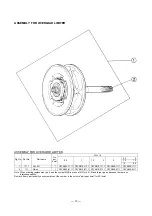
Page 34: ...C3YA010 1111 C3YA015 1111 C3YA020 1111 C3YA025 1111 2 111 Pinion 1 C3YA005 9111 C3YA010 9111 C3YA015 9111 C3YA020 9111 C3YA025 9111 Note When ordering replacement part use the symbol M3B in place of M...

Page 35: ...th the following EC directives and standards EC directives Machinery Directive 2006 42 EC Harmonized standards EN ISO 12100 1 and EN ISO 12100 2 Safety of machinery EN 818 7 2002 A1 2008 Short link ch...

Page 36: ...AX 49 0 211 528009 59 E mail info kito europe eu URL http www kito net KITO corporation Tokyo Head office SHINJUKU NS Building 9F 2 4 1 Nishi Shinjuku Shinjuku ku Tokyo 163 0809 Japan URL http www kit...

Page 37: ......

Reviews: