background image

6

13.  Be sure the timer start and timer reset button covers align 

with contact points on control board.

14.  Be sure the LED lens and digital display line up with holes in 

bezel.

15.  Using thumbs, press control PCB board until it clamps 

securely into cradle.

16.  Reassemble the ferrite bead fastener with one Phillips screw. 

Be sure 5-pin connector is securely connected to power 
supply PCB. Reassemble base to cradle.
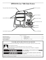
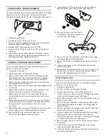
Button Replacement

There are three (3) push buttons on the control bezel: power 
on/off, timer start and timer reset:

1. Unplug 

the 

waffl e baker.

2.  Remove the base; see Component Access.

3.  Remove one screw from the ferrite bead fastener.

2.  

Using thumbs, push down on control PCB board (located in 
cradle arm) until clamps release.(See Figure 1) 

3.  

Place tape over button front. This will help prevent losing the 
button’s small spring. 

4.  

Reach inside the waffl e baker cradle and grasp the button 
cover sleeve with needle nose pliers. Pull straight back to 
release the sleeve. 

5.  

Remove tape and pull out button cover and shaft from bezel, 
being careful not to lose small spring. 
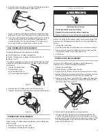
6.  

Insert new button shaft through bezel hole. Be sure spring is 
between button top and outer bezel. (See Figure 6)

7.  

Slide button cover over shaft. Add a small drop of super glue 
or solder into the cover hole. (See Figure 7)

8.  

Be sure button cover lines up with contact point on control 
PCB board. 

9.  

Using thumbs, press control PCB board until it clamps 
securely into cradle. Reassemble.

10.  Check each button and the timer adjustment knob to make 

sure each works properly.

Figure 6

Figure 7

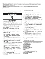
CONTROL PCB BOARD REPLACEMENT

The control board regulates the light, timer and power on/off 
button. It is located in the cradle.

1. Unplug 

the 

waffl e baker.

2.  Remove the base; see Component Access.

3.  

Remove one Phillips screw from the ferrite bead fastener. 
Then remove the white, 5-pin connector from the power 
PCB. This will allow for easy access to the control PCB.

4.  

Remove the timer adjustment knob; see Timer Adjustment 
Knob Replacement instructions.

5.  

Remove the start and reset buttons; see Button Replacement 
instructions.

6.  

Remove the control PCB from the cradle. Remove (4) four 
Phillips screws from the control PCB plastic cover.

7.  

Remove three (3) white pin connectors from bottom of 
control board; two (2), 2-pin connectors and one (1), 5-pin 
connector. 

8.  

Replace the old control PCB with the new control PCB. Be 
sure three white (3) pin connectors are connected securely 
to board; two (2), 2-pin connectors and one (1), 5-pin 
connector. 

9.  

Reassemble with new control PCB board to the plastic cover 
with 4 Phillips screws. Slide control board into cradle.

10.  Reassemble the timer adjustment knob; see Timer 

Adjustment Knob Replacement instructions.

12.  Slide button cover over shaft. Add a 

small drop of super glue or solder into 
the cover hole. (See Figure 7)

11.  Insert button shaft through bezel hole. Be sure spring is 

between button top and outer bezel. (See Figure 6)

POWER SUPPLY PCB REPLACEMENT

The power supply printed circuit board (PCB) provides DC voltage 
to power the control PCB located in the cradle arm and AC 
voltage to the heating elements in the waffl e plates. (See Figure 5)

1. Unplug the waffl e baker.

2.  Remove base; see Component Access.

3.  

Remove six (6) blue-capped black and white AC leads from 
the power supply PCB located in the base.

4.  

Remove white, 5-pin connector from the PCB.

5.  

Remove four (4) Phillips screws from PCB; remove board 
from base.

6.  

Reassemble with new board. Be sure six (6) blue-capped 
leads and white 5-pin connector are connected securely in 
their proper positions. Replace base cover.

Figure 5

Summary of Contents for Pro Line KPWB100

Page 1: ...1 PRO LINE WAFFLE BAKER SERVICE MANUAL Model KPWB100 8204590 Table of Contents 2 ...

Page 2: ... symbol alerts you to potential hazards that can kill or hurt you and others All safety messages will follow the safety alert symbol and either the word DANGER or WARNING These words mean follow instructions instructions DANGER WARNING KPWB100 Pro Line Waffle Baker Features Table of Contents Waffle Bake Features 2 Safety Recommendations 3 Tool Recommendations 3 Electrical Requirements 4 Service Pre...

Page 3: ...rvice technician is aware of the operating safeguards recommended to the customer 1 Read the Pro Line Series Waffle Baker Instructions and Recipes booklet 2 Do not touch hot surfaces Use handles or knobs 3 To protect against electrical shock do not immerse cord plugs or waffle baker in water or other liquids 4 Close supervision is necessary when any appliance is used by or near children 5 Unplug w...

Page 4: ...e needed to bake two waffles one cup batter each on the two waffle plates Longer baking times will produce darker crispier waffles For your first waffles a good starting time is 3 minutes 30 seconds The baking time can be set in 15 second increments from a minimum of 2 minutes 30 seconds to maximum of 5 minutes 30 seconds Waffle Plate Temperature Pre heat waffle baker then measure the temperature ...

Page 5: ...y working dial thermometer will indicate Cool Temperature ambient temperature Preheat Temperature ambient temperature to 350º F Ready 350º F If the dial thermometer is warped or the needle does not move to indicate waffle plate temperature changes replace the dial thermometer 1 Unplug the waffle baker 2 Remove black screw cover located left of the unit s top hinge See Figure 2 Component Access Acc...

Page 6: ...cradle 1 Unplug the waffle baker 2 Remove the base see Component Access 3 Remove one Phillips screw from the ferrite bead fastener Then remove the white 5 pin connector from the power PCB This will allow for easy access to the control PCB 4 Remove the timer adjustment knob see Timer Adjustment Knob Replacement instructions 5 Remove the start and reset buttons see Button Replacement instructions 6 ...

Page 7: ...efective or worn out SOLUTION First adjust baking time If too light increase the baking time if too dark decrease baking time If the problem persists The wires thermistor and heating elements in the clamshell unit cannot be repaired or replaced Replace unit according to warranty PROBLEM Waffle baker will not turn on display remains dark will not heat CAUSE The waffle baker uses 1400 watts total wi...

Page 8: ...vegetable or mineral oil with a paper towel on the discolored area The normal color will return PROBLEM One or more of the four black clips on the back of the waffle baker break CAUSE Defective material or user damage SOLUTION The black clip that holds the stainless steel cover in place may be replaced The clips that hold the clamshell together are not replaceable PROBLEM Owner upset about formald...

Page 9: ...ature Parts 8204569 Guide Use Care 8204590 Repair Parts List 8204592 Wiring Diagram 2 8211486 Button Start 3 8211487 Button Power 4 8211489 Lens LED 5 8211485 Knob 6 8211488 Bezel 7 8211490 Screw 8 8211491 MCU PCB Assembly 9 8211513 Bracket Knob 10 8211508 Cover Button 11 8211492 Nameplate 12 8211493 Holder PCB 13 8211514 Spring ...

Page 10: ...8 Clamp 2 Cap 8211497 Pearl Metallic 8212149 Nickel Pearl 3 8211499 Holder Axle 4 Base 8211496 Pearl Metallic 8212148 Nickel Pearl 5 8211494 Bracket 6 8211495 Screw 7 8211500 Power Supply 8 8211505 Cover Bottom 9 8211503 Clamp Cord 10 8211501 Feet 11 8211502 Screw 12 8211504 Cover Spring 13 8212256 Cord Power Incl MOV Board ...

Page 11: ...11 Notes ...

Page 12: ...tchenAid U S A KitchenAid Canada licensee in Canada Emploi sous licence par KitchenAid Canada au Canada 2008 All rights reserved Tous droits reserves Todos los derecchos reservados Specifications subject to change without notice Les specifications sont sujettes à changement sans préavis Especificaciones sujetas a cambio sin previo aviso 8204590 Printed in U S A 02 2008 ...

Reviews: