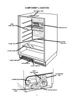
background image

6

EVAPORATOR ASSEMBLY

The evaporator and heat exchanger is one assembly.  The capillary tube and suction tube are cap-
tured  inside a metal "sandwich".  Refrigerant circulates through a cavity that is molded into the evapo-
rator assembly.

The evaporator is secured to the back wall of the inner cabinet liner with screws and can be removed
if replacement is necessary.

The capillary tube is routed inside the suction line.  The entire heat exchanger assembly is accessible
by removing the back panel of the wine cellar.

Removing the Evaporator

To remove the evaporator, first follow the steps to remove the back panel of the wine cellar on page 5
and follow the procedure for purging the sealed system found in the Job Aid, 

Sweep Charge Proce-

dures for the 90's

, Part No. LIT4321717.

1. Disconnect the electric power from the appliance.

2. Score and snap off the capillary tube at the inlet to the filter-dryer.

3. Unbraze the suction line from the compressor inlet.

4. Remove the two (2) screws securing each of the bottle racks to the sides of the cabinet liner

and remove all of the bottle racks.

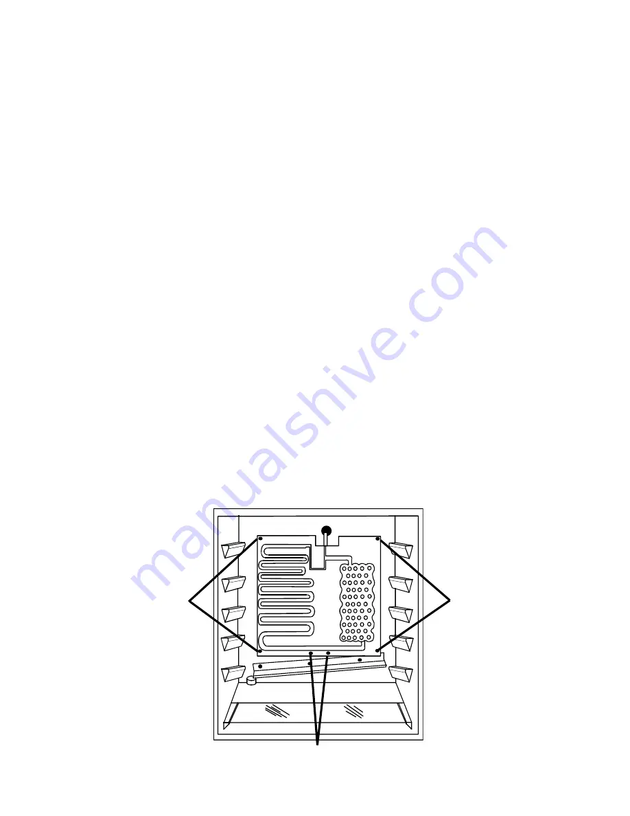
5. Loosen the two (2) philips-head thermostat sensor retainer screws at the bottom of the evapo-

rator.

6. Remove the four (4) philips-head screws securing the evaporator to the back wall of the

cabinet liner.

7. Carefully pull the evaporator from the unit making sure the heat exchanger passes through

the access hole in the back of the cabinet without snagging or damaging the foam insulation
on the outside back of the unit.

REMOVE THESE

SCREWS

REMOVE THESE

SCREWS

LOOSEN THESE SCREWS

Summary of Contents for KUWS246

Page 1: ...I TECHNICAL EDUCATION KUWS246 WINE CELLAR JOB AID 4317201 KAR 5 ...

Page 2: ...nd its companion video Part No 4321718 GOALS AND OBJECTIVES The goal of this Job Aid is to provide detailed information that will enable the service technician to properly diagnose malfunctions and repair the 60 bottle capacity wine cellar The objectives of the Job Aid are The service technician will Understand proper safety precautions Successfully troubleshoot and diagnose malfunctions Successfu...

Page 3: ... Cycle Defrost 4 Reversible Door 4 Door Adjustment 4 SECTION THREE COMPONENT ACCESS 5 Component Compartment 5 Evaporator 6 SECTION FOUR TROUBLESHOOTING AND DIAGNOSIS 7 Troubleshooting Guide 7 Refrigeration System Diagnosis 8 Compressor Winding Resistance 8 SECTION FIVE TECH TIPS 9 Wiring Diagram 9 Strip Circuits 9 Serial and Model Number Designation 10 Product Specification and Warranty Informatio...

Page 4: ...R CORD GROUNDING PRONG A separate adequately fused and grounded circuit should be available for this appliance Do not remove any grounding wires from individual components while servicing unless the component is to be removed and replaced It is extremely important to replace all grounding wires when components are replaced To avoid the risk of electrical shock property damage personal injury or de...

Page 5: ...V ...

Page 6: ...ions Disposal Procedure R134a REFRIGERANT SERVICE INFORMATION This product uses R134a refrigerant This refrigerant requires synthetic ester oil in the compressor This cooling system does not tolerate contamination from any of the following Other Refrigerants Moisture Petroleum based Lubricants Silicone Lubricants Cleaning Compounds Rust Inhibitors Leak Detection Dyes Any Other Type of Additive As ...

Page 7: ...2 COMPONENT LOCATION INTERIOR LIGHT THERMOSTAT CONDENSER DRAIN CUP DRAIN TROUGH WIRE WINE RACK GLASS SHELF LIGHT SWITCH COMPRESSOR CONDENSER FAN HEAT EXCHANGER CAPILLARY TUBE FILTER DRYER EVAPORATOR ...

Page 8: ...ient temperature of 72 F Turning the control counter clockwise a lower number to raise the temperature inside the wine cellar Turning the control clock wise a higher number will lower the temperature A number of factors will affect the internal temperatures of the cabinet 1 Setting of the temperature control 2 Ambient room temperature 3 The number of times the door is opened and closed 4 The lengt...

Page 9: ... the two 2 screws securing the bottom hinge to the door 2 Remove the two 2 screws securing the top hinge to the door 3 Remove the door from the unit 4 Remove the three 3 screws securing the top hinge to the cabinet 5 Invert the top hinge and install it on the bottom opposite side of the cabinet 6 Remove the three 3 screws securing the bottom hinge to the cabinet 7 Invert the bottom hiinge and inta...

Page 10: ...side If the compressor is to be replaced 6 Remove the four 4 hex head screws securing the back of the cabinet to the base plate 7 Loosen but do not remove the two 2 hex head screws securing the front of the cabinet to the base plate 8 Remove the hex head screw securing the condenser fan scroud to the cabinet 9 Tilt the cabinet forward and insert a block of wood on each side between the cabinet and...

Page 11: ... sealed system found in the Job Aid Sweep Charge Proce dures for the 90 s Part No LIT4321717 1 Disconnect the electric power from the appliance 2 Score and snap off the capillary tube at the inlet to the filter dryer 3 Unbraze the suction line from the compressor inlet 4 Remove the two 2 screws securing each of the bottle racks to the sides of the cabinet liner and remove all of the bottle racks 5...

Page 12: ...4 Defective compressor 1 Temperature control setting too cold 2 Thermostat defective 1 Door gasket not sealing properly 2 Door out of alignment 1 Tubing touching cabinet 2 Fan blade touching shroud 3 Fan blade touching obstruction such as wiring foam insulation packaging material 1 Unit is not level 2 Defrost drain plugged 3 Drain trough spout and drain cup not aligned 4 Kinked drain tube 1 Defros...

Page 13: ... cold may frost heavily Warm near room temp Warm near room temp Room temp cool Room temp cool COMPRESSOR WINDING RESISTANCE To measure start winding resistance measure across the Common C and Start S pins To measure run winding resistance meausre across the Common C and the Run R pins When measuring resistance between the Common C Start S or Run R pins to ground meter should read infinity Any resi...

Page 14: ...9 TECH TIPS Section Six WIRING DIAGRAM STRIP CIRCUITS N COMPRESSOR OVERLOAD THERMOSTAT L1 RELAY ROCKER SWITCH DOOR SWITCH LAMP L1 N COOLING CIRCUIT LAMP CIRCUIT ...

Page 15: ... KitchenAid Brand K Product Identification U Undercounter Built in Product Identification W Wine Cellar Features S Standard Width in Inches Capacity 6 60 Bottles of Wine Year of Introduction Color WH White BL Black Engineering Changes numeric K U W S 24 6 E WH 0 FOR PRODUCT SPECIFICATIONS AND WARRANTY INFORMATION ON KITCHENAID BRAND CALL 1 800 422 1230 The model number for the KitchenAid 60 bottle...

Page 16: ...VI Inc For the way it s made ...

Reviews: