KITCHENAID
Stand Mixer Service Manual LIT4177310-C 2005 KitchenAid
The control plate is spaced 3/8” from the
mounting bracket for the proper speed setting
“Starting Point.”
Plug the mixer into a watt meter set at the proper
voltage.
Turn the mixer to “Stir Speed.” The mixer may or
may not start. If not, turn the two mounting screws
out evenly until mixer starts. Adjust both screws
evenly until a speed setting of 40 (40 - 64) is
attained.
Turn mixer to speed #6. The single screw at the
bottom of the control plate is used to control this
speed; adjust to attain a speed of 150 (141 - 170 ).
Turn speed control to speed #8, pause, then turn
to speed #10. There should be a noticed speed
increase between #8 and #10 speeds. If not, back
speed #6 down slightly until there is at least a
minor speed change between #8 and #10.
The #10 speed should be at least 185 (185 - 250).
When proper speeds have been set, lock the two
lock nuts on the upper mounting screws using an
11/32” wrench.
Be careful not to move the mounting screws in or
out during the locking process.
Recheck speeds after locking the nuts, and if a
fine adjustment is needed, it can be done without
loosening the locking nuts.
G.
Place the trimband (Fig. 81) on the gearcase -
motor housing, and with the two # 6-32 x 3/16”
screws, fasten it to the housing.
Tuck in all the wire leads- insure no wires are
pinched - and place the end cover
on the end of the motor housing and secure it with
the # 6-32 x 3/8” oval head screw (Fig. 82).
H.
With the end cover on the machine, test the
speeds again to make sure no change took place in
the control plate.
With mixer working correctly, place the bowl on
the bowl screw cap.
Place the flat beater on the agitator shaft.
There should be approximately 1/16” clearance
between the bowl and beater.
If the beater is too close to the bowl, turn the
beater height adjusting screw “out” or “in” if it is
too far away (Fig. 83).
The mixer is now ready for operation.
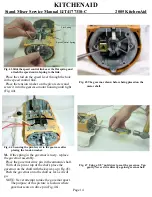
Fig. 81. Replace the trim band on the gearcase after
speeds have been set.
Fig. 82. The end cover is secured to the mixer with a
tapered head screw.
Fig. 83 The beater height adjustment screw used to set
the 1/16” clearance between the bowl and beater.
Page 24


