background image

1-2

KITCHENAID MODEL & SERIAL NUMBER DESIGNATIONS

MODEL NUMBER

SERIAL NUMBER

MODEL NUMBER

K UI A 15 NR H S

0

INTERNATIONAL SALES IND.
OR MARKETING CHANNEL
IF PRESENT

PRODUCT GROUP

K = KITCHENAID

PRODUCT IDENTIFICATION

UI = UNDERCOUNTER ICE MAKER

MERCHANDISING SCHEME

A = ARCHITECT

C = CULINARY & ARCHITECT II

S = STANDARD

O = OUTDOOR

V = SIGNATURE SERIES

CAPACITY / SIZE / SERIES / CONFIGURATION

15 = 15" WIDE
18 = 18" WIDE

FEATURES

PR = PUMP, RIGHT HAND DOOR SWING
PL = PUMP, LEFT HAND DOOR SWING
PN = PUMP, NON-REVERSIBLE DOOR SWING
NR = NON-PUMP, RIGHT HAND DOOR SWING
NL = NON-PUMP, LEFT HAND DOOR SWING
NN = NON-PUMP, NON-REVERSIBLE DOOR SWING

YEAR OF INTRODUCTION

H = 1999, J = 2000, K = 2001, L = 2002, S = 2006, T = 2007

COLOR CODE

B = BLACK, W = WHITE, S = STAINLESS
T = BISCUIT, M = METEORITE

ENGINEERING CHANGE (NUMERIC)

SERIAL NUMBER

E T 04 54321

DIVISION RESPONSIBILITY

E = EVANSVILLE, IN

YEAR OF PRODUCTION

T = 2006, U = 2007

WEEK OF PRODUCTION

04 = 4th WEEK

PRODUCT SEQUENCE NUMBER

Summary of Contents for Kitchen Aid KAR-19

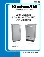
Page 1: ...CHNICAL EDUCATION JOB AID 4317408 KAR 19 2007 DESIGN 15q 18q AUTOMATIC ICE MAKERS KUIA15NRH 11 KUIA15PRL 11 KUIA15NLH 11 KUIA15PLL 11 Denotes Color Designation KUIA18NNJ 11 KUIA18PNL 11 Intoductory Models ...

Page 2: ...m and Strip Circuits used in this Job Aid are typical and should be used for training purposes only Always use the Wiring Diagram supplied with the product when servicing the ice maker GOALS AND OBJECTIVES The goal of this Job Aid is to provide detailed information that will enable the In Home Service Professional to properly diagnose malfunctions and repair the KitchenAid 2007 Design 15 18 Automa...

Page 3: ...ts 4 5 Removing The Water Recirculation Pump 4 7 Removing The Reservoir Drain Pump Water Level Sensor 4 8 Removing The Condenser Fan Motor 4 9 Removing The Evaporator 4 12 Removing The Measured Fill Water Valve 4 16 Removing The Hot Gas Valve Solenoid 4 17 Removing The Condenser 4 18 Removing The Compressor 4 19 Removing The Internal Drain Pump 4 21 Removing The Ice Maker Door Gasket 15 Models 4 2...

Page 4: ...fect On Making Ice 6 1 Troubleshooting Chart 6 2 Diagnostic Flow Chart For Ice Maker Control Board 6 5 WIRING DIAGRAM STRIP CIRCUITS 7 1 Wiring Diagram 7 1 Strip Circuits 7 2 TECH TIPS 8 1 Cleaning The Ice Maker 8 1 Cleaning The Evaporator Plate 8 1 Page ...

Page 5: ...kill or hurt you and others All safety messages will follow the safety alert symbol and either the word DANGER or WARNING These words mean All safety messages will tell you what the potential hazard is tell you how to reduce the chance of injury and tell you what can happen if the instructions are not followed You can be killed or seriously injured if you don t immediately follow instructions You ...

Page 6: ...RIES CONFIGURATION 15 15 WIDE 18 18 WIDE FEATURES PR PUMP RIGHT HAND DOOR SWING PL PUMP LEFT HAND DOOR SWING PN PUMP NON REVERSIBLE DOOR SWING NR NON PUMP RIGHT HAND DOOR SWING NL NON PUMP LEFT HAND DOOR SWING NN NON PUMP NON REVERSIBLE DOOR SWING YEAR OF INTRODUCTION H 1999 J 2000 K 2001 L 2002 S 2006 T 2007 COLOR CODE B BLACK W WHITE S STAINLESS T BISCUIT M METEORITE ENGINEERING CHANGE NUMERIC S...

Page 7: ...1 3 MODEL SERIAL NUMBER LABEL LOCATION The Model Serial Number label location is shown below Model Serial Number Location ...

Page 8: ...Exterior Dimensions W x D x H 15 or 18 x 24 x 34 381 or 457 2 x 609 6 x 863 6 mm Exterior Finish Stainless Steel or Painted Steel Net Weight 15 94 lbs 42 6 kg 18 123 lbs 55 8 kg Cube Thickness Control Water Level Sensor Control Board Setting Harvest Control Thermistor under Evaporator Bin Ice Level Control Thermistor on side of Bin Refrigerant R134a Ambient Temperature 55 to 100 F Water Pressure 2...

Page 9: ...ire or electrical shock IMPORTANT If this product is connected to a GFCI Ground Fault Circuit Interrupter pro tected outlet nuisance tripping of the power supply may occur resulting in the loss of cool ing Ice quality may be affected If nuisance tripping has occurred and if the condition of the ice appears poor dispose of it Recommended Grounding Method For personal safety this appliance must be g...

Page 10: ...he copper tubing to meet the water line inlet located on the back of the ice maker cabinet as shown below CONNECTING THE WATER LINE 1 Turn off the main water supply 2 Turn on the nearest faucet and allow it to run long enough to clear line of water 3 Find a 1 2 12 70 mm to 1 1 4 3 18 cm vertical cold water pipe near the ice maker NOTE A horizontal pipe will work but drill on the top side of the pi...

Page 11: ...ide diameter Drain lines must have a 1 drop per 48 2 54 cm drop per 122 cm of run or 1 4 drop per 12 6 35 mm per 30 48 cm and not have any low points where water can settle The floor drains must be large enough to accommodate drainage from all drains The ideal installation has a standpipe with a 1 1 2 3 81 cm to 2 5 08 cm PVC drain reducer installed directly below the outlet of the drain tube as s...

Page 12: ...structions can result in death fire or electrical shock WARNING WARNING 1 Plug in ice maker or reconnect power WARNING WARNING Excessive Weight Hazard Use two or more people to move and install ice maker Failure to do so can result in back or other injury 2 Style 1 For gravity drain system push the ice maker into position so that the ice maker drain tube is positioned over the PVC drain reducer St...

Page 13: ...nit is R134a There are two very important additions to the refrigeration system in the ice maker the Hot Gas Valve and the Condenser Accumulator Tube The components operate as follows Hot Gas Valve Allows high pressure refrigerant gas to bypass the condenser and flow through the condenser accu mulator tube CondenserAccumulator Tube Hot gas pushes liquid refrigerant through the accumulator tube int...

Page 14: ...s circulated to clean the system of minerals and contaminates The hardness of the water supplied to the ice maker will affect the quality of the ice that is produced It may also affect the operation of the water system Awater softener or poly phosphate feeder will notcurealloftheproblemsassociatedwithhard water but they can be used to reduce scale buildup in the ice maker NOTE Some poly phosphate ...

Page 15: ...er Recirculation Pump Reservoir Pan Water Level Sensor Reservoir Drain Pump Water Return Tube Water Valve Outlet Tube Measured Fill Water Inlet Valve From Water Supply Bin Drain Manual Drain Drain Overflow WATER SYSTEM COMPONENT LOCATIONS ...

Page 16: ...3 4 ELECTRICAL SYSTEM The ice maker s electrical system provides power for the refrigeration and water systems and controls the operation of each component ...

Page 17: ...pressor During the Freeze mode some of the hot gas that is in the condenser accumulating tube condenses to a liquid and remains in the ac cumulating tube During the later stages of the Freeze mode as the ice slab forms on the evaporator freezing plate some of the refrigerant passing through theevaporatorwillnotevaporateintoagas but will remain a liquid This liquid refrigerant will settle in the ac...

Page 18: ...orator tem perature begins to rise When the evaporator thermistor reaches the set temperature 52 F the unit switches to the Freeze mode This cy cling between Freeze and Harvest continues until the ice bin is full The electronic control board operates the vari ous components and systems in the ice maker for each of the Freeze and Harvest modes CLEAN MODE Electrical System The electronic control boa...

Page 19: ...nd hold the button again to turn off the feature The Holiday mode LED is lite constantly in this mode Order Component On Off LED On for some models Service LED Off for some models Clean LED Feature Light for some models 1 Entry into Test Mode ON ON ON ON 2 Bin Thermistor ON Solid OK 2 blinks Open 4 blinks Short OFF OFF OFF 3 Evaporator Thermistor OFF OFF ON Solid OK 2 blinks Open 4 blinks Short OF...

Page 20: ...inlet andthenintothedrainpump chamber As the water level rises it bridges the full contacts and the pump starts to run The pump discharges the water through the outlet andthecheckvalve Whenthe full connection is removed the pump runs for an additional 12 seconds to empty the tank If the water level in the drain pump continues to rise due to a slow or blocked drain or a blocked vent hose and touche...

Page 21: ...NENT ACCESS Push button Switch Electronic Control Board Light Switch Dual Transformer Evaporator NOTE The Evaporator Thermistor Is Located On Tubing Below Evaporator Cutter Grid Water Recirculation Pump Reservoir Drain Pump Compressor Condenser Fan Motor Hot Gas Valve Solenoid Behind Condenser Measured Fill Water Valve Condenser Accumulator Tube Condenser Bin Thermistor Water Level Sensor ...

Page 22: ...hermistor out of the retain ing clamp and remove it 7 To remove the cutter grid a Disconnect the cutter grid and bin thermistor connectors from the bottom of the control housing b Remove the two hex head screws from both sides of the cutter grid The longer screw and white spacer are on the right side Retaining Clamp Bin Thermistor Connector Bin Thermistor Connector Cutter Grid Connector Cutter Gri...

Page 23: ...urface Be careful not to scratch the ice maker liner d Removethespacerfromtherightcutter grid bracket tab Cutter Grid Ice Guides Spacer Cutter Grid d Reach behind the accumulator and unclip the evaporator thermistor from the evaporator tubing and remove it Evap Thermistor Connector Control Housing Water Trough Screws Water Trough Continued on the next page Accumulator Evaporator Thermistor Bottom ...

Page 24: ...he unit see step 7 on page 4 2 for the proce dure b Pull out on the left and right water dis tributor retainers and remove the tabs from the slots in the evaporator Pull the distributor forward and remove the water hose Water Distributor Water Hose Water Distributor Tab ...

Page 25: ...sing so that you can access the components 4 Control Housing Screws NOTE The control housing components con sist of 1 Electronic control board 2 Dual transformer 3 Light switch 4 Push button switch assembly 7 To remove the electronic control board a Disconnect the six harness connectors from the board terminals b Remove the two mounting screws Continued on the next page Control Panel 1 3 2 4 Six 6...

Page 26: ... the model number of the ice maker The service replace ment switch is not supplied with a decorative overlay 9 To remove the light switch or push but ton switch assembly a Peel off the decorative overlay from the front of the control housing Locking Arm Light Switch b Disconnect the molex plug from switch assembly Press the back of switch as sembly and push the switch assembly out of the housing D...

Page 27: ...bracket 8 Disconnect the two wire recirculation and drain pump connectors from the harness block 9 Remove the two thumbscrews from the reservoir and remove the reservoir from the ice maker 10 Remove the recirculation pump outlet tube 11 Remove three hex headed screws from the pump mounting bracket and remove pump assembly 12 Separate the recirculation pump from the bracket Thumbscrew Screw Thumbsc...

Page 28: ...ction b Remove the pump retaining screw and bracket c Rotate the pump 1 4 turn and pull it down and out of reservoir Water Reservoir Water Recirculation Pump Shield Screw 6 To remove the water level sensor a Disconnectthewaterlevelsensorelec trical connection b Remove the retaining clips if present c Pull the sensor up and out of the bracket Screw Water Level Sensor Electrical Shock Hazard Disconn...

Page 29: ...valve to drop down out of the way NOTE If the unit you are servicing is equipped with an internal drain pump perform steps 9 and 10 If the unit does not have an internal pump skip those steps and proceed to step 11 on the next page 9 From the back of the unit remove the four screws from the unit compartment cover and remove the cover Unit Compartment Cover 4 Screws Water Inlet Tubing Measured Fill...

Page 30: ...e shroud assembly back towards the compressor and then lift and remove the assembly from the unit 11 Tilt the front of the cabinet up until you can access the two side screws on the condenser fan motor shroud and secure the cabinet so that it cannot tip forward or backward Tubing Internal Drain Pump Condenser Fan Motor Left Side Shroud Screw Continued on the next page Condenser Fan Motor Bottom Sh...

Page 31: ...de straight off the shaft NOTE Makesurewhenreinstallingthefan blade that the blade is seated completely on motor shaft Condenser Fan Motor Screw 1 of 2 15 Remove the two hex head screws from the condenser fan motor and remove it from the shroud Condenser Fan Blade ...

Page 32: ...ew from the ice maker door and pull the door off the bot tom hinge 7 Remove the two 5 16 hex head screws from the top hinge and remove the hinge Hinge Screws 8 Remove the two front and two rear screws from the cabinet top 2 Hex Head Screws Screw Screw 9 Lift the cabinet top and position it forward on top of the unit Top Door Screw REMOVING THE EVAPORATOR Electrical Shock Hazard Disconnect power be...

Page 33: ...ve the cover 12 Remove the four screws from the unit com partment cover and remove the cover Unit Compartment Cover 4 Screws Channel Cover 6 Screws 13 Cut the tie wrap from around the tubing and wire harness inside the channel Tie Wrap 14 Remove the two screws from the reservoir water trough and remove the trough Screw Screw Water Trough Counterbalance Plate 18 Models Screw 1 of 6 Continued on the...

Page 34: ...os at the top of the next col umn 17 Pull out on the left and right water distribu tor retainers and remove the tabs from the slots in the evaporator disconnect it from the hose and remove it 18 Remove the four screws from the evapo rator then carefully lift the evaporator just high enough to remove the two right spacers Evaporator 19 Remove the Permagum from the liner channel 2 Screws Spacers 2 S...

Page 35: ...nd discharge the refrigerant into an approved recovery system IMPORTANT Refrigerant lines must be connected by a licensed EPA certified refrigerant technician in accordance with established procedures 23 Unbraze and cut the evaporator from the tubing at the following locations Suction line at the compressor Hot gas line at the hot gas valve Cut capillary tube at the drier filter Suction Line Hot G...

Page 36: ...or towel under the valve to catch water 7 Disconnect the water inlet and outlet tub ing from the quick disconnect fittings on the measured fill water valve Front Panel Screws 8 Disconnect the two electrical connectors from the valve Bracket Screws Two Electrical Connectors Outlet Tube Inlet Tube Measured Fill Valve Measured Fill Valve Electrical Shock Hazard Disconnect power before servicing Repla...

Page 37: ...lve see step 3 for the procedure b Access the sealed system and dis charge the refrigerant into an approved recovery system IMPORTANT Refrigerant lines must be connected by a licensed EPA certified refrigerant technician in accordance with established procedures c Unbraze the hot gas valve from the tubing REASSEMBLYNOTE Wheninstallingthenew hotgasvalve useagenerousamountofthermal heat trap paste b...

Page 38: ...cedure 4 Remove the two mounting screws from the condenser bracket flanges 5 Access the sealed system and discharge the refrigerant into an approved recovery system IMPORTANT Refrigerant lines must be connected by a licensed EPA certified refrigerant technician in accordance with established procedures 6 Unbrazethetwocondenserjointsfromthe tubing 2 Condenser Bracket Screws Condenser Tubing Joints ...

Page 39: ...e the terminal cover using a stan dard screwdriver Insert the screwdriver into the cover slot and press down to unsnap and remove it Compressor Terminal Cover Cover Slot 7 Remove the wires from the ground termi nal the overload protector terminal and the relay terminal 8 Pull the overload protector and relay from the compressor pins Ground Wire Overload Protector Relay Electrical Shock Hazard Disc...

Page 40: ...filter 14 Unbraze the compressor suction and dis charge joints from the tubing Filter Drier 2 Clips Metal Spacers Rubber Isolators Discharge Line 15 Pull the two clips off the front compressor mounting studs 16 Lift the compressor off the four mounting studs and remove it from the unit Remove thefourmetalspacersandrubberisolators from the compressor stud locations Suction Line Perform the followin...

Page 41: ...Compartment Cover 4 Screws 5 Loosen the clamps and pull the ends of thethreewaterlinesfromtheinternaldrain pump 6 Disconnect the power cord plug from the internal drain pump 7 Remove the two mounting screws from the internal drain pump Ends Of 3 Water Lines Screws Power Cord Plug 8 Remove the internal drain pump from the unit Internal Drain Pump Electrical Shock Hazard Disconnect power before serv...

Page 42: ...Open the ice maker door b Pull the gasket out of the door track NOTE Besuretocheckthenewgasket for a proper seal after you install it Top Door Screw 1 To remove the door remove the top door screw from the ice maker door and pull the door off the bottom hinge Door Gasket Door Track ...

Page 43: ...emovethetwotopandtwobottomscrews from the grille and remove it from the front of the ice maker 3 Open the ice maker door and remove the four front hinge screws 2 per hinge and remove the door NOTE Support the door while you remove the screws to avoid it from falling off the unit 2 Removetheendofthespringfromthedoor bracket and the screw on some models from the bottom of the door hinge Bottom Grill...

Page 44: ... cap from the door Bottom Door Cap Screws Handle Cap Screw 1 of 3 6 Peel the gasket from the grooves in the door and remove the gasket Door Channel 7 Removethesixscrewsfromtheinnerdoor panel and remove the panel Inner Door Panel Screw 1 of 6 Gasket Door Insulation 8 Slide the door insulation out of the top of the outer door panel Outer Door Panel ...

Page 45: ...Channel Supports Outer Door Panel 10 Slide the bottom door cap off the channel supports Channel Supports Hinge Pin Channel Support Door Hinge Channel Support 11 To remove the door hinge pull the hinge pin out of the channel support and remove the hinge Door Hinge Hinge Pin Continued on the next page ...

Page 46: ...oor panel between the tabs and the inside edge of the top door cap Tab Inside Edge Of Top Door Cap 3 When you reinstall the inner door panel slide the edge under the door handle as shown below Top Door Cap Inner Door Panel 4 Before you reinstall the grille position the insulation pads and the air block as shown below Air Block Insulation Pads ...

Page 47: ...isconnect power 2 Set the ohmmeter to the appropriate scale 3 For the most accurate measurement immerse the thermistor in ice water for 5 minutes then use the 32 F 0 C reading in the chart 4 Touch the ohmmeter test leads to the two bin thermistor connectors The meter should indicate as shown in the following chart Refer to page 4 2 for the procedure for access ing the evaporator thermistor 1 Unplu...

Page 48: ...ale 3 Touch the ohmmeter test leads to the primary black and white leads of the dual transformer The meter should indicate between 3 5 and 4 5 ohms 4 Touch the ohmmeter test leads to the sec ondary yellow and yellow leads of the dual transformer The meter should indicate between 0 11 and 0 14 ohms 5 Touch the ohmmeter test leads to the secondary red and red leads of the dual transformer The meter ...

Page 49: ...roximately 3 6 ohms RESERVOIR DRAIN PUMP Refer to page 4 8 for the procedure for access ing the reservoir drain pump 1 Unplug ice maker or disconnect power 2 Set the ohmmeter to the appropriate scale 3 Touch the ohmmeter test leads to the outside reservoir drain pump wire con nector pins The meter should indicate approximately 3 6 ohms Electrical Shock Hazard Disconnect power before servicing Repl...

Page 50: ...ENSOR Refer to page 4 8 for the procedure for access ing the water level sensor 1 Run the diagnostic tests see page 3 7 and check for the proper operation of the water level sensor in step 4b 2 With the water level sensor immersed in water the Service LED should stay on solid 3 Withthewaterlevelsensoroutofthewater the Service LED should blink Electrical Shock Hazard Disconnect power before servici...

Page 51: ...e for ac cessing the measured fill water valve Refer to page 3 7 for diagnostic mode 1 Unplug ice maker or disconnect power 2 Unsnap and remove the cover from the measured fill water valve 3 Set the ohmmeter to the appropriate scale 4 Touchtheohmmetertestleadstothemea sured fill water valve solenoid terminals The meter should indicate between 240 and 280 ohms MEASURED FILL WATER VALVE Electrical S...

Page 52: ...cate a closed circuit 0 ohms Relay Coil Spade Terminal Run M Start S Run M Start S Spade Terminal Start S Run M Common C Refer to page 4 19 for the procedure for ac cessing the compressor 1 Unplug ice maker or disconnect power 2 Set the ohmmeter to the appropriate scale 3 To test the compressor windings a Touch one of the ohmmeter test leads to the Common C pin and the other lead to the Start S pi...

Page 53: ...esium Carbonates Staining Aesthetics only Scale Scale 1 Use only Ice Machine Cleaner P N 4396808 Use only Ice Machine Cleaner P N 4396808 2 Water softener and iron filter 1 Abrasive cleaning 2 Polyphosphate feeder or water softener reduces or eliminates need for abrasive cleaning 1 2 Polyphosphate feeder or water softener reduces frequency of cleaning by 50 RECOMMENDATIONS Water softeners or polyp...

Page 54: ...or has unit shut off Customer Instruction Ice touching bin thermistor Normal operation Water supply turned off Turn on water supply Loose or missing reservoir cap Tighten or replace Water slide return tube out of reservoir R eposition tube Inlet tube out of position and missing reservoir R eposition tube Water inlet tube frozen near evaporator Thaw and reposition tube Defective inlet water valve T...

Page 55: ...circulating pump R epair or replace the pump motor assembly Partially blocked water distributor Clean distributor and evaporator Compressor is not running Test compressor relay and overload Blocked condenser or stalled fan motor Clean condenser repair or replace motor Unit is in the startup mode Wait 5 minutes and recheck R oom temperature below 55 F 13 C Bin thermistor has unit shut off Customer ...

Page 56: ...e see procedure on page 8 1 Grinding cavitating sound from recirculation pump If the reservoir is full replace the pump Noisy drain pump R epair or replace Ice freezing together in the bin Normal This is normal with low customer useage Cloudy soft thin or poor tasting ice Poor water quality S ee chart on page 6 1 Open or disconnected bin thermistor or thermistor wiring Test thermistor wiring harne...

Page 57: ...6 5 DIAGNOSTIC FLOW CHARTS FOR ICE MAKER CONTROL BOARD OVERVIEW ...

Page 58: ...rface is changed to On from Off Clean or Holiday This will be the initial time it is turned on or when the ice maker is turned on after the completion of the Clean or Holiday Modes or drain pump models only when operation resumes after the ice maker is shut down by the drain pump ...

Page 59: ...6 7 Freeze Mode Time in this mode is dependent on the water level in the reservoir There is no minimum time and the maximum time is 25 minutes ...

Page 60: ...6 8 Harvest Mode Time in this mode will be 2 to 17 minutes dependent on the condition of the evaporator thermistor ...

Page 61: ...6 9 Harvest Bin Not Full ...

Page 62: ...6 10 Harvest Bin Full ...

Page 63: ... this mode is dependent on the temperature at the bin thermistor NOTE Bin Full set point is 36 F The ice maker will stay in the Idle Mode as long as the ice in the bin touches the bin thermistor and keeps it lower than 36 F ...

Page 64: ...ng 3 blinks look for an evaporator thermistor that has not reached 52 F This may be due to a loose or improperly positioned thermistor a hot gas failure a sealed system leak or restriction The bin thermistor is constantly checked during the Flush Idle and Harvest Modes and the end of each Freeze Mode If the LED is flashing 2 blinks look for a disconnected or open bin thermistor ...

Page 65: ... Clean Mode may only be selected while the ice maker is turned off at the user interface NOTE At the end of the Clean Mode the ice maker will stay OFF The reservoir is to be drained by the consumer prior to restarting the ice maker ...

Page 66: ...6 14 NOTES ...

Page 67: ...7 1 WIRING DIAGRAM STRIP CIRCUITS WIRING DIAGRAM MEASURED FILL WATER VALVE ...

Page 68: ...k Rd Bu Rd Bk GY Water Recirculation Pump Wh Bu Yl Rd Bk Transformer Bk Wh Water Valve Electronic Smart Valve Electronic Smart Valve Reservoir Drain Pump Bk Rd Bu Rd Bk GY Wh Bk Or Wh Transformer Rd Wh Overload Compressor Relay Electronic Control Water Recirculating Pump Condenser Fan ...

Page 69: ...r Valve Electronic Smart Valve Electronic Control Reservoir Drain Pump Hot Gas Solenoid Overload T Electronic Control Bk Rd Bu Rd Bk Wh Vi Wh Transformer Bk Rd Wh Overload Compressor Relay Electronic Control Bk Rd Bu Yl Rd Bk Wh Transformer o Water Recirculation Pump Reservoir Drain Pump Hot Gas Solenoid ...

Page 70: ...7 4 NOTES ...

Page 71: ...lways wear rubber gloves when handling cleaning solutions Continued on the next page CLEANING THE EVAPORATOR PLATE NOTE Use one 16 oz 473 ml bottle of Ice Machine Cleaner Part Number 4396808 For best performance do not use any other type of ice machine cleaner in the ice maker 1 Press and hold the OFF keypad to turn the unit off 2 For easier access to the evaporator re move the cutter grid see pag...

Page 72: ...iedwiththeicemachine cleaner IMPORTANT Usetheentirebottletoclean the unit 6 Openthebottleandpourasmallamountof cleaning solution onto the cleaning brush NOTE If a brush is not available you may use a non scratching blue Scotch Brite pad Cleaning Solution On Pad 9 Press and hold the Clean keypad The Clean light will blink to show that the Clean cycle is in progress When the light turns off after ap...

Page 73: ...E PROFESSIONAL IN CANADA FOR PRODUCT SPECIFICATIONS AND WARRANTY INFORMATION CALL 1 800 488 4791 FOR TECHNICAL ASSISTANCE WHILE AT THE CUSTOMER S HOME CALL THE TECHNICALASSISTANCE LINE 1 800 832 7174 HAVE YOUR STORE NUMBER READY TO IDENTIFY YOU AS AN AUTHORIZED IN HOME SERVICE PROFESSIONAL FOR WHIRLPOOL PRODUCTS 1 800 253 1301 FOR KITCHENAID PRODUCTS 1 800 422 1230 FOR ROPER PRODUCTS 1 800 447 673...

Page 74: ......

Reviews: