background image

6

Install Anti-Tip Bracket

1. 

Remove the anti-tip bracket that is taped inside the upper 

oven with the package containing literature.

2. 

Determine which mounting method to use: floor or wall. If 

you have a stone or masonry floor, you can use the wall 

mounting method.

3. 

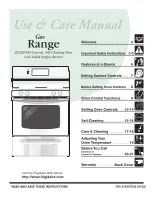
Determine and mark edge of range in the cutout space. The  

mounting bracket can be installed on either the left side or 

right side of the cutout. Position mounting bracket in cutout 

so that right (or left) edge of the bracket is 

15

/

16

" (2.4 cm) from 

the marked edge of the range, as shown.
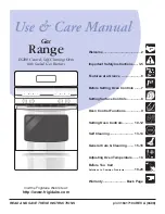
4. 

Drill two 

1

/

8

" (3.0 mm) holes that correspond to the bracket 

holes of the determined mounting method. See the following 

illustrations.

5. 

Using a Phillips screwdriver, mount anti-tip bracket to the 

wall or floor with the two #12 x 1

5

/

8

" screws provided.

WARNING

Tip Over Hazard

A child or adult can tip the range and be killed.
Install anti-tip bracket to floor or wall per installation 

instructions.
Slide range back so rear range foot is engaged in the 

slot of the anti-tip bracket.
Re-engage anti-tip bracket if range is moved.
Do not operate range without anti-tip bracket installed 

and engaged.
Failure to follow these instructions can result in death 

or serious burns to children and adults.

A

B

C

A.  Anti-tip bracket
B.  Mark edge of 

range.

C. 

15

/

16

" (2.4 cm)

A

B

Floor Mounting

Wall Mounting

A

B

A.  #12 x 1

5

/

8

" screws

B.  Anti-tip bracket

A.  #12 x 1

5

/

8

" screws

B.  Anti-tip bracket

Summary of Contents for KFED500EWH03

Page 1: ...ement est bien installée et engagée 18 Réglage de l aplomb de la cuisinière 19 Achever l installation 20 Déplacement de la cuisinière 20 Table of Contents Table des matières W10694065B IMPORTANT Save for local electrical inspector s use IMPORTANT À conserver pour consultation par l inspecteur local des installations électriques RANGE SAFETY You can be killed or seriously injured if you don t immed...

Page 2: ...at are shown must be used Given dimensions are minimum clearances The floor anti tip bracket must be installed To install the antitip bracket shipped with the range see the Install Anti Tip Bracket section Grounded electrical supply is required See the Electrical Requirements section IMPORTANT To avoid damage to your cabinets check with your builder or cabinet supplier to make sure that the materi...

Page 3: ...imum when bottom of wood or metal cabinet is covered by not less than 1 4 0 64 cm flame retardant millboard covered with not less than No 28 MSG sheet steel 0 015 0 4 mm stainless steel 0 024 0 6 mm aluminum or 0 020 0 5 mm copper 30 76 2 cm minimum clearance between the top of the cooking platform and the bottom of an uncovered wood or metal cabinet A 353 4 1 8 90 8 cm 0 3 cm cooktop height minim...

Page 4: ...aluminum cable See the Electrical Connection U S A Only section Allow 2 to 3 ft 61 0 cm to 91 4 cm of slack in the line so that the range can be moved if servicing is ever necessary A UL Listed conduit connector must be provided at each end of the power supply cable at the range and at the junction box Wire sizes and connections must conform with the rating of the range The wiring diagram is locat...

Page 5: ...nder range 2 Remove oven racks and parts package from inside oven 3 To place range on its back take 4 cardboard corners from the carton Stack one cardboard corner on top of another Repeat with the other 2 corners Place them lengthwise on the floor behind the range to support the range when it is laid on its back 4 Using 2 or more people firmly grasp the range and gently lay it on its back on the c...

Page 6: ...ket holes of the determined mounting method See the following illustrations 5 Using a Phillips screwdriver mount anti tip bracket to the wall or floor with the two 12 x 15 8 screws provided WARNING Tip Over Hazard A child or adult can tip the range and be killed Install anti tip bracket to floor or wall per installation instructions Slide range back so rear range foot is engaged in the slot of the...

Page 7: ...cord through the strain relief in the cord conduit plate on bottom of range Allow enough slack to easily attach the wiring to the terminal block Tighten strain relief screw against the power supply cord WARNING Electrical Shock Hazard Disconnect power before servicing Use a new 40 amp power supply cord Plug into a grounded outlet Failure to follow these instructions can result in death fire or ele...

Page 8: ...nstallation following instructions for your type of electrical connection 4 wire recommended 3 wire if 4 wire is not available Electrical Connection Options If your home has And you will be connecting to Go to Section 4 wire receptacle NEMA type 14 50R A UL Listed 250 volt minimum 40 amp range power supply cord 4 wire connection Power Supply Cord 4 wire direct A fused disconnect or circuit breaker...

Page 9: ...lock posts with 10 32 hex nuts 7 Securely tighten hex nuts NOTE For power supply cord replacement only use a power cord rated at 250 volts minimum 40 amps or 50 amps that is marked for use with nominal 13 8 3 5 cm diameter connection opening with ring terminals and marked for use with ranges 8 Replace terminal block access cover 9 Slide range back so rear range foot is under the anti tip bracket S...

Page 10: ...p the insulation back 1 2 5 cm from the end of each wire 2 Allow enough slack in the wire to easily attach the wiring terminal block 3 Complete electrical connection according to your type of electrical supply 4 wire or 3 wire connection 4 wire Connection Direct Wire Use this method for New branch circuit installations 1996 NEC Mobile homes Recreational vehicles In an area where local codes prohib...

Page 11: ... range back so rear range foot is under the anti tip bracket See the Verify Anti Tip Bracket is Installed and Engaged section 3 wire connection Direct Wire Use this method only if local codes permit connecting ground conductor to neutral supply wire 1 Pull the conduit through the hole and conduit plate on bottom of range Allow enough slack to easily attach the wiring to the terminal block 2 Attach...

Page 12: ...the bracket Verify that the bracket is held securely in place by the mounting screws 4 Slide the range forward and verify that the anti tip bracket is securely attached to the floor or wall 5 Slide range back so the rear range foot is inserted into the slot of the anti tip bracket IMPORTANT If the back of the range is more than 2 5 1 cm from the mounting wall the rear range foot may not engage the...

Page 13: ... slide range onto cardboard or hardboard to avoid damaging the floor covering If removing the range is necessary for cleaning or maintenance For power supply cord connected ranges 1 Slide range forward 2 Unplug the power supply cord 3 Complete cleaning or maintenance 4 Plug power supply cord into a grounded outlet 5 Slide range back so rear range foot is under anti tip bracket 6 Refer to the Verif...

Reviews: