Page
11
Note:
Do not use COM_2 on the Remote Display.
For
AC2430
model:
The 24V model is capable to connect in parallel. Connect two
AC2430
in parallel will provide a
total of 24V 60A charging current.
Use on single
AC2430
charger
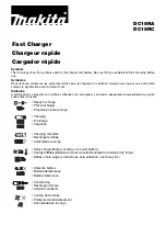
•
To install the optional Remote Display in a specific location, a 6 pin standard RJ12 cable
(maximum length 25 ft) is required.
•
Install the standard RJ12 cable in your desired location.
•
Connect one end of the RJ12 cable to the Digital Display Port and the other end of the
cable to the COM_1 port on the Remote Display Panel. Please note polarity.
•
The Remote Display is now ready for use.
Note:
Do not use COM_2 for a single
AC2430
charger connection.
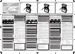
Use on two
AC2430
chargers connected in parallel
•
To install the optional Remote Display in a specific location, two 6 pin standard RJ12
cables (maximum length 25 ft) are required.
•
Install the two standard RJ12 cables in parallel in your desired location.
•
For the first RJ12 cable, connect one end to the Digital Display port of Charger_1 and the
other end to Remote Display Panel COM_1 Port.
•
For the second RJ12 cable, connect one end to the Digital Display port of Charger_2 and
the other end to Remote Display Panel COM_2 Port.
•
The Remote Display is now ready for use.
Note 1:
With AC Input available, both Digital Displays will show ‘
CON
’ indicating the two
chargers are connected in parallel. The ‘
INFO
’, ‘
NEXT
’ and ‘
SET
’ push buttons on both
chargers are disabled. With AC Input not available, press and hold the ‘
INFO
’ button on
Charger_1 will show battery voltage of Bank 1, 2, 3 and then follow with charger firmware
revision.
Note 2:
The combined chargers setting are based on the original setting on Charger_1. To
readjust the combined charger setting, it has to be done through the Remote Display.
Before connecting the batteries to the chargers, Battery Bank 1 of Charger_1 has to connect
to Battery Bank 1 of Charger_2. Battery Bank 2 of Charger_1 has to connect to Battery
Bank 2 of Charger_2 and Battery Bank 3 of Charger_1 has to connect to Battery Bank 3 of
Charger 2. The Common Ground of both chargers has to be connected together. Damage
to both chargers may occur with wrong connection if the above connections are not follows.
Tips:
During installation or unit setting, it is recommended to pre-set the desire charger
setting on Charger_1 first before connect the 2
nd
RJ12 cable to Charger_2, as once
Charger_2 is connected, all the three push button on the charger is disable and the display
will only show ‘Con’ and the setting can only be adjusted by using the Remote Panel.
Optional Temperature Sensor Connection:
For battery banks connect to a single charger.
•
To install the temperature sensor, simply connect the RJ12 plug from the sensor to the RJ12
Temperature Sensor Port on the charger located near the Interface Port.
•
On the Temperature Sensor end, simply connect the ring terminals to the negative terminal of
one of the chosen battery banks. As Battery Bank 1 is for the main battery bank charging, it is
highly recommended to connect the Temperature Sensor to Battery Bank 1 when in use.
For battery banks connect to two AC2430 chargers in parallel:
•
Two batteries Temperature Sensor are required.
•
Connect RJ12 plug from Temperature Sensor 1 to the RJ12 Temperature Sensor Port on
charger 1. On the Temperature Sensor end, simply connect the ring terminals to the positive
terminal of the main battery bank.
•
Two batteries Temperature Sensor are required.
•
Connect RJ12 plug from Charger Temperature Sensor 2 to the RJ12 Temperature Sensor
Port on charger 2. On the Temperature Sensor end, simply connect the ring terminals to the
negative terminal of the main battery bank.
Summary of Contents for Abso Charger 12V 20A
Page 1: ...Abso Charger 12V 20A AC1220 12V 40A AC1240 12V 60A AC1260 24V 30A AC2430 Owner s Manual ...
Page 19: ...Page 19 ...
Page 20: ...Page 20 ...
Page 21: ...Page 21 Appendix B ...