


PT568 Service Manual
11
on the master radio will light red, and the data of the master is sent
to the slave. While the slave is receiving the data, the LED lights
green. When cloning of data is completed, the LED of the master
will go out, and the slave will restart automatically.
4. Carry out the operation in step 3 to clone other slave radios.
Note: The user can enable or disable the wired clone function
through PC programming software. Once the wired clone function
is disabled, the radio cannot enter the Wired Clone Mode.
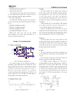
Chapter 5 Disassembly for Repair
The radio is a piece of precision communication equipment.
Please be careful when disassemble the radio during service. The
instructions for the disassembly are as follows.
5.1 Attaching and Removing the Battery
1) Attaching the Battery
Fit the two extensions at the top of the battery into the slots at
the top of the radio’s body.
Press the bottom part of the battery towards the radio until a
click is heard and the battery is hooked.
2) Removing the Battery
Push the battery latch at the bottom of the radio forward, the
bottom part of the battery will bounce up automatically. Then
release the belt clip and remove the battery from the radio’s body.
Note:
* Do not short-circuit the battery terminals or dispose battery
in fire.
* Do not disassemble the battery casing by yourself.
5.2 Installing/Removing the belt clip
Match the two holes of the belt clip with those on the rear of
the radio, and then fix the belt clip to the radio using the two
supplied 2.5*8 .0 screws. Loose the fixing screws to remove the
belt clip.
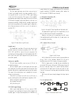
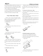
5.3 Removing the chassis from the front cabinet
1. Pull out the volume knob and the channel selector knob, and
remove the antenna;
2. Remove the two nuts for knobs and the nut for the antenna
connector by the special tool;
3. Remove the two fixing screws at the lower part of the Al
chassis by a hexagonal screwdriver;
4. Insert a flat-blade screwdriver into the slot at the bottom of the
Al chassis, and prize it up. Then pull the Al chassis backwards to
remove it from the front cabinet. Be careful not to break the
speaker wire.
5. Remove the solder of the speaker wire with a soldering iron.
Then you can remove the chassis from the front cabinet.
See figure below:
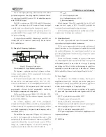
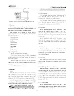
5.4 Removing the mainboard from the Al chassis
1. Remove the top waterproof gasket and the top gasket;
2. Remove the screws on the PCB by a cross screwdriver;
3. Remove the solder of the antenna connector with a soldering
iron, and remove the mainboard.
See figure below:
After the aforesaid disassembly, you can repair and adjust the
radio according to its actual malfunction.


