


8
1.1.4
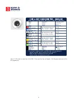
The (optional) CNF 4 connector
The optional ventilator CNF 4 for the CNR 1 has separate wires for heating and ventilation. In case the heater is
used also the ventilator should be active. The other way around the ventilator can be used without heating. When
the ventilation unit is mounted later on the CNR 4, the extra bottom plate mounts to the bottom of the CNR 4. The
(S) and (T) cables run on both sides of the ventilator to the back of the CNF 4 housing. The extra cover that comes
with the CNF 4 slides under the CNR 4 cover. The 4 pins connector on the back of the CNF 4 is shown below. The
CNR 4 without CNF 4 is supplied with an extra serial number label. This can be used to put on the bottom of the
CNF 4 when mounted (later) on the CNR 4.
Figure 1.3 The heater and ventilator connections of the CNF 4.
1.1.5
Using the CNR 4 calibration factors
The pyranometer generates a mV signal that is simply proportional to the incoming solar Radiation. The conversion
factor between voltage, V, and Watts per square metre of solar irradiance E, is the so-called calibration constant C
(or sensitivity).
For each pyranometer
E = V/C
(1.1)
When using the pyrgeometer, you should realise that the signal that is generated by the pyrgeometer represents the
exchange of Far Infrared (thermal) radiation between the pyrgeometer and the object that it is facing. This implies
that the pyrgeometer will generate a positive voltage output, V, when it faces an object that is hotter than its own
sensor housing, and that it will give a negative voltage signal when it faces an object that is colder. This means that
for estimating the Far Infrared radiation that is generated by the object that is faced by the pyrgeometer, usually the
sky or the soil, you will have to take the pyrgeometer temperature, T, into account. This is why a the temperature
sensors are incorporated in the CNR 4's body near the pyrgeometer sensing element, and has therefore the same
temperature as the pyrgeometer sensor surface. The calculation of the Far Infrared irradiance, E, is done according
to the following equation:
For the pyrgeometer only E = V/C + 5.67
⋅
10
-8
*T
4
(1.2)
In this equation C is the sensitivity of the sensor. Please bear in mind that T is in Kelvin, and not in Celsius or
Fahrenheit.
Red
Rot • Rouge • Rojo
Wire
Kabel
Fil
Cable
Green
Grün • Vert • Verde
Yellow
Gelb • Jaune • Amarillo
Function
Funktion
Fonction
Función
5 Watt ventilator
12 VDC
Ventilator • Ventilateur • Ventilador
10 Watt heater
12 VDC
Heizung • Chauffage • Calentador
Blue
Blau • Bleu • Azul
Connect with
Anschluss an
Relier à
Conectar con
+
-
-
+
2
4
1
3
CNF 4 VENTILATION UNIT
(OPTIONAL • OPTION • OPTION • OPCIONAL)
4 WIRE CABLE • 4-ADRIGES KABEL • CÂBLE 4 FILS • CABLE DE 4 CONDUCTORES
Ground *
Erde
Terre
Tierra
Housing
Gehäuse
Boîte
Cubierta
Shield
Abschirmung
Protection
Malla
1
2
3
4


