Kipp & Zonen CNR 4 Instruction Manual Download Page 23


22 

2.3


Properties of the pyrgeometer  


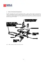
The  pyrgeometer  consists  of  a  thermopile  sensor  and  a  silicon  window  integrated  in  the  CNR  4  body.  The 
thermopile is coated with a black absorbent coating. The paint absorbs the radiation and converts it to heat. The 
resulting heat flow is converted to a voltage by the thermopile. Most electrical specifications are determined by the 
thermopile and the resistor. 
Spectral  specifications  are  determined  by  the  absorber  paint  and  the  window.  The  window  serves  both  as 
environmental protection and as a filter. It only transmits the relevant Far Infrared radiation, while obstructing the 
Solar radiation. The upper thermopile has a dome shaped window so that its field of view is 180 degrees, and that 
its  angular  characteristics  fulfil  the  so-called  cosine  response  as  much  as  possible,  in  this  field  of  view.  It  causes 
water droplets to run of more easily. 
The field of view of the lower pyrgeometer is 150 degrees. It is limited due to the use of a flat window. This does 
not produce a large error because the missing part of the field of view does not contribute significantly to the total, 
and is compensated for during calibration.  
 
There  is  no  international  standard  that  classifies  pyrgeometers.  Pyrgeometers  have  two  specific  properties  that 
deserve  special  attention.  The  first  is  the  so-called  window-heating  offset;  the  second  is  the  influence  of  water 
deposition on the window. 


2.3.1


Window heating offset 


The window heating offset is a measurement error that is introduced by the heating of the pyrgeometer window by 
the sun. It only occurs during the day. During a sunny day, the upper pyrgeometer will suffer from this. This error 
can be reduced by shading or ventilating. On a sunny windless day with a solar irradiance of 1000W/m

2

, an error of 

6 Watts per square meter can be expected. The window will absorb part of the solar radiation and will heat up. As a 
result  of  this  heating,  heat  will  irradiate  towards  the  thermopile.  This  results  in  an  error  source,  in  the  Infrared 
range. This error is neglected, however, in the net radiation calculation this is justified because the solar radiation is 
always  dominant  when  this  error  occurs.  Due  to  its  construction  the  window  heating  offset  in  the  CNR  4  is 
extremely small compared with other instruments. 


2.3.2


Water deposition on the pyrgeometer window 


The second specific error source of a pyrgeometer is the substantial measurement error introduced as the result of 
water  deposition  on  the  window.  Water  will  completely  obstruct  the  transmission  of  Far  Infrared  radiation.  Water 
deposition will occur when it rains, snows, or when dew is deposited. 
In the case of rain or snow, the resulting error is not very significant, mainly due to the fact that under these cloudy 
conditions, the pyrgeometer signal will be close to zero anyway. The cloud base temperature is generally close to 
ambient temperature. The conditions under which dew can form are much more likely to produce significant errors. 
A  typical  situation  occurs  at  night,  with  a  cloudless  sky,  low  wind  speeds,  and  high  humidity  (so-called  clear, 
windless  nights).  Under  these  conditions,  the  upward-facing  pyrgeometer  signal  is  large,  typically  -100  Watts  per 
square  metre.  When  dew  occurs,  this  reading  can  drop  to  zero,  resulting  in  a  100  Watts  per  metre  square  error. 
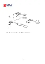
Generally speaking this kind of error is too large, and if possible it should be avoided. Ventilation and heating can 
prevent dew deposition with the CNR 4's optional CNF 4. Heating will keep the instrument window above the dew 
point and ventilation will keep the domes clean from rain and snow. 

2.3.3


Specifications of the Pyrgeometer  


The output of the pyrgeometer is a small voltage, in the mV range. It is proportional to the temperature difference 
between the pyrgeometer and the object that it faces. This implies that for calculation of the absolute quantity of 
Far Infrared radiation, that is emitted by the sky or the ground you also need to take the pyrgeometer temperature 
into account. This temperature is measured by a Pt-100 that is incorporated in the body of CNR 4. The calculation of 
the Far Infrared irradiance is described in chapter 1. 


Pyrgeometer Specification 

Unit 

Value 

Spectral range 

µm 

4.5 to 42 (50% points) 


Summary of Contents for CNR 4

Page 1: ...Net Radiometer CNR 4 Instruction Manual...

Page 2: ...LITY Kipp Zonen guarantees that the product delivered has been thoroughly tested to ensure that it meets its published specifications The warranty included in the conditions of delivery is valid only...

Page 3: ...nder our sole responsibility that the product Type CNR 4 Name Net Radiometer To which this declaration relates is in conformity with the following standards Imissions EN 50082 1 Group standard Emissio...

Page 4: ...f the pyranometer 18 2 2 2 Spectral properties of the pyranometer 20 2 2 3 Directional Cosine response of the pyranometer 20 2 3 Properties of the pyrgeometer 22 2 3 1 Window heating offset 22 2 3 2 W...

Page 5: ...ient air flow over the domes and windows to minimize the formation of dew and reduce the frequency of cleaning The integrated heater can be used to melt frost The CNR 4 specifications when used with C...

Page 6: ...as also 8 pins but only 6 wires are coming out of the cable Exchanging the connectors will not damage the CNR 4 To prevent mix up of the cables after installation it is advised to mark the cables with...

Page 7: ...rgeometer Upper Oben Sup rieur Superior Pyrgeometer Lower Unten Inf rieur M s bajo Blue Blau Bleu Azul Connect with Anschluss an Relier Conectar con Yellow Gelb Jaune Amarillo Green Gr n Vert Verde Ho...

Page 8: ...d covered with a black sleeve If the CNR 4 rod is grounded to the mast it is advised not to connect the shielding on the data logger side This might cause ground loops and offsets in the signal Figure...

Page 9: ...ween the pyrgeometer and the object that it is facing This implies that the pyrgeometer will generate a positive voltage output V when it faces an object that is hotter than its own sensor housing and...

Page 10: ...in a positive signal To measure the Far Infrared irradiances with the two pyrgeometers separately the Pt 100 output is required The formula 1 2 is used to calculate the Far Infrared irradiance of the...

Page 11: ...39 100 78 101 17 101 56 101 95 102 34 102 73 103 12 103 51 103 90 104 29 104 68 105 07 105 46 105 85 106 24 106 63 107 02 107 40 107 79 108 18 108 57 108 96 109 35 109 73 110 12 110 51 110 90 111 28...

Page 12: ...2952 2854 Table 1 2 Resistance values versus temperature in C of the CNR 4 s thermistor Relatively small errors occur when the CNR 4 is not in thermal equilibrium This happens for example when the hea...

Page 13: ...pyranometer E lower pyranometer 1 4 In this formula E is calculated according to formula 1 1 Net Solar radiation will always be positive Checking this can be used as a tool for quality assurance of y...

Page 14: ...ature column nine tracks the ambient temperature Under cloudy conditions this is logical cloud bases will be colder than the ambient temperature at instrument level the temperature difference depends...

Page 15: ...e upper pyrgeometer Figure 1 2 3 clear day for the downward facing pyrgeometer Upper pyrgeometer day with alterna3ng cloud elds pyrgeometer U_emf Sensi3vity W m Temp YSI 44031 C Upwelling signal downw...

Page 16: ...cooling The sky and the ground temperature can be calculated from the measured values of the sensors using formulas 1 6 and 1 7 day night Cloudy clear 20 C 20 C pyrgeo Up pyrgeo low pyrano up pyrano...

Page 17: ...g improve the accuracy significantly Due to the fact that the Net Solar radiation can be very intense 1000 Watts per square metre compared to a typical 100 for the Net Far Infrared radiation the accur...

Page 18: ...ature C 40 to 80 CE according to EC guideline 89 336 EEC 73 23 EEC Environmental protection IP 67 2 2 Properties of the pyranometer The pyranometer consists of a thermopile sensor and a glass dome bot...

Page 19: ...sensitivity N S 40 C to 10 C 4 10 C to 40 C N S 40 C to 80 C Definition Maximum error due to any change of instrument temperature within the indicated temperature interval Tilt error 1 Definition Max...

Page 20: ...nition Deviation of the product of spectral absorption and spectral transmittance from the corresponding mean within the indicated spectral range Uncertainty in daily total 5 95 confidence level Defin...

Page 21: ...t absorbs all radiation from all wavelengths Its field of view is 180 degrees The directional properties are similar to that of a blackbody Another way of expressing these directional properties is to...

Page 22: ...sponse or cosine response of the pyranometer On the horizontal axis the zenith angle is shown 0E zenith angle equals 90E angle of incidence The vertical axis shows the deviation from the ideal cosine...

Page 23: ...range This error is neglected however in the net radiation calculation this is justified because the solar radiation is always dominant when this error occurs Due to its construction the window heatin...

Page 24: ...indow heating offset W m 6 0 to 1000 W m solar irradiance Definition Caused by heating of the dome due to solar radiation Field of view Upper detector Lower detector 180 150 Definition Sensor opening...

Page 25: ...ectivity of the total instrument 2 3 5 Directional Cosine response of the pyrgeometer The measurement of the Far Infrared radiation falling on a surface also called irradiance or radiative flux requir...

Page 26: ...e significant Dew deposition will probably take place under conditions with large Far Infrared irradiation from the pyrgeometer detector to the clear sky typically minus 100 Watts per metre square Und...

Page 27: ...A table stating the resistance values can be found in table 1 1 The thermistor has a much larger resistance value than the Pt 100 also the change in resistance with respect to temperature in absolute...

Page 28: ...librated against the World Reference at WMO in Davos 3 3 Recalibration of pyranometers and pyrgeometers We suggest recalibration for all sensors pyranometers and pyrgeometers to be performed every two...

Page 29: ...nt by less than 1 The Net Radiometer should be installed horizontally using the level on the body of the CNR 4 For installation in buildings or in solar energy applications you will often have to moun...

Page 30: ...or cover black part in picture below can be removed by just pulling it down from the CNR 4 The filter needs to be checked for dust and particles every 6 12 months It can be cleaned by simply washing i...

Page 31: ...e starting the second test measurement let the pyranometer rest for at least five minutes to let it regain its thermal equilibrium For testing set a voltmeter to its most sensitive range setting Darke...

Page 32: ...ermistor Using a meter which measures resistance you can check the operation of the thermistor If connected properly the resistance of two wires of the thermistor should be measured The value can be r...

Page 33: ...bject The top U bolts allow rotation of the CNR 4 rod while the extra screw under the front U bolt allows the rod to tilt All mounting material for fixation to a horizontal or vertical pole is include...

Page 34: ...33 Fig 7 2 CMB 1 mounting examples with CNR 4 albedometer and pyranometer...

Page 35: ...clude the following items A delivery includes One CNR 4 One mounting rod Two cables Two drying cartridges Four calibration values on 2 calibration sheets long and short wave One CD with instruction ma...

Page 36: ...Here recalibration to the highest standards can be performed at low cost Recalibration can usually be performed within four weeks If required urgent recalibration can be accomplished in three weeks or...

Page 37: ...ro de repuestos Passion for Precision Go to www kippzonen com for your local distributor or contact your local sales office HEAD OFFICE Kipp Zonen B V Delftechpark 36 2628 XH Delft P O Box 507 2600 AM...

Reviews: