background image


1-137

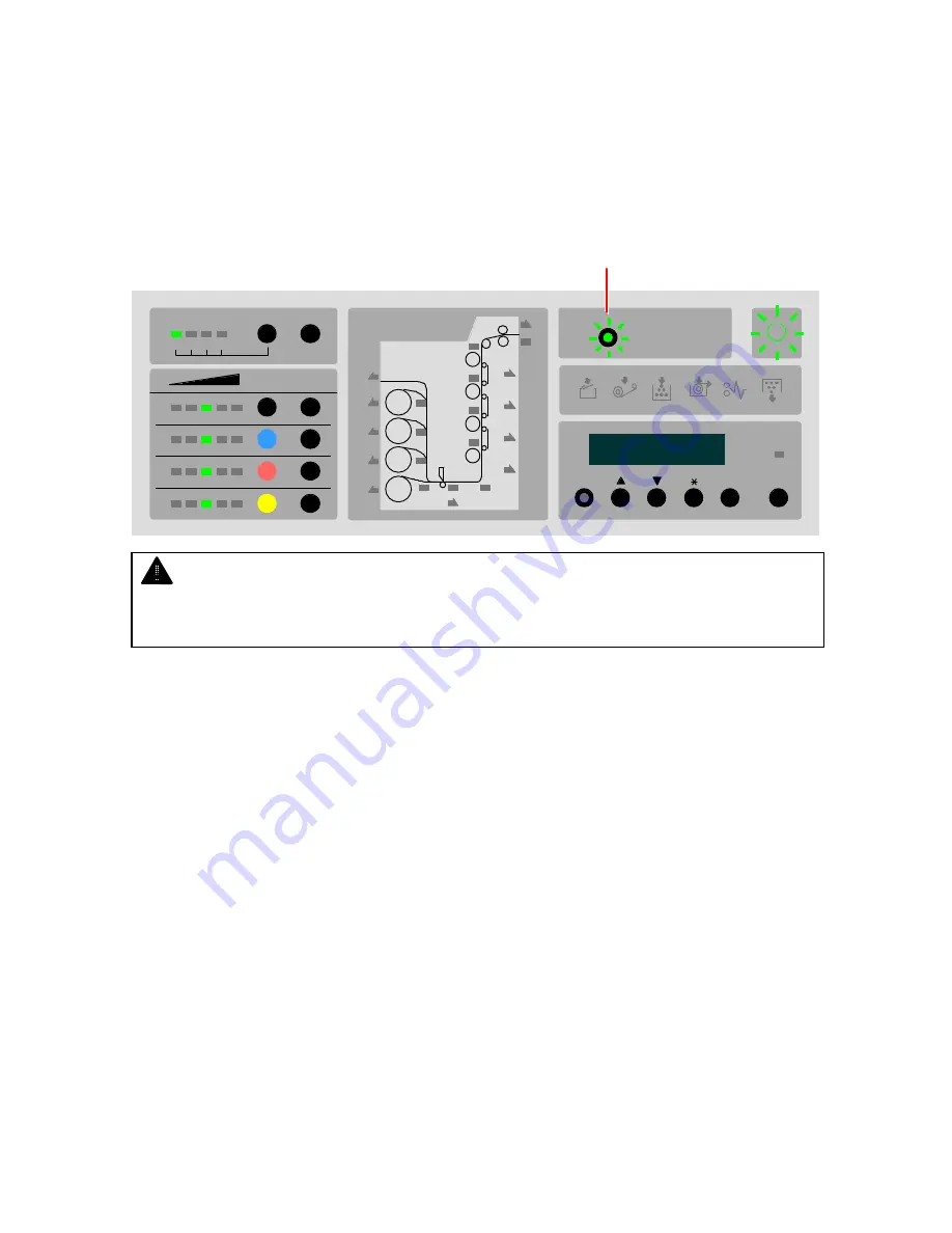
3. 6. 2     Flash of Wire-Clean Key 

 
The Wire-Clean Key may flash green synchronized with the Ready Indicator when turning on the 
KIP Color 80. When it is flashing, the wire of the internal imaging component is automatically 
cleaned to avoid the image problem. It stops flashing automatically when wire cleaning is 
completed. 
 
Please refer to [1.3.7.1 Unnecessary vertical line image on the print] on page 1-140 for the effect of 
Wire Cleaning. 
 
 
                                                                                              Wire-Clean Key 


1

2 3 4

Paper Deck

K

C

M

Y

MF

D1

D2

D3

D4

D5

D6

D7

D8

D9

D10

Wire-Clean

Menu

Enter

Online

Copy Density

Select

Cut


NOTE 

 
Automatic wire cleaning is performed only when the KIP Color 80 is turned on after long term 
of power off. 

Summary of Contents for KIP Color 80

Page 1: ...Version A3 KIP Color 80 Printer Operator s Guide Guide 2...

Page 2: ...noise or flickering may occur Use a separate power line and install the PRINTER as far as possible from said equipment The International ENERGY STAR Office Equipment Program is an international progr...

Page 3: ...Manual and have the following meaning WARNING This WARNING mark means that there is a possibility of death or serious injury if you ignore or do not follow the said instruction Safety Warnings CAUTIO...

Page 4: ...part inside of the printer 2 Do not disassemble or tamper with the printer It may result in a fire or electrical shock 1 Do not plug in the printer into a multi wire connector in which some other equ...

Page 5: ...r electric shock 2 If you do not use the printer for a long duration holidays company shutdown turn off and unplug the printer from the outlet for safety Do not pull the cord when you unplug the print...

Page 6: ...E 2132 1 48 2 9 5 User Mode 05 Temporary clear E 2232 1 50 2 9 6 User Mode 06 Temporary clear E 2332 1 52 2 9 7 User Mode 07 Temporary clear E 2432 1 54 2 9 8 User Mode 08 Temporary clear E 2142 1 56...

Page 7: ...3 3 11 Transportation Unit 4 open Code U 0120 1 124 3 3 12 Fuser Cover open Code U 0130 1 125 3 3 13 Fuser Upper Cover open Code U 0131 1 125 3 3 14 Waste Toner Door open Code U 0140 1 125 3 3 15 Wast...

Page 8: ...SING Keep the equipment away from water sources boilers humidifiers or refrigerators 5 The installation site must not have open flames dust or ammonia gases 6 The equipment should not be exposed to th...

Page 9: ...said Governments 4 Do not copy Government issued revenue stamps certificate stamps that are prescribed by Liquor Tax Act or the Commodity Tax Act Special items which require your attention 1 The gover...

Page 10: ...ironmental condition To attain constant image quality in changing environmental conditions several printing parameters are adjusted automatically Please note that the printer must still be installed w...

Page 11: ...220Vac line voltage First print time Shorter than 45 seconds A0 or E Fusing method Roller heat pressure fusing Development Contact type mono component non magnetic development system Charging method...

Page 12: ...50 89 F Humidity 30 to 70 RH Storage condition of consumables Print media Wrap the media surely to shut out the humidity Toner Keep the toner cartridge away from the direct sunlight and store it in th...

Page 13: ...ration Panel Indicates information like printer status error mis feed location and etc Roll Decks 4 rolls of media can be installed Media Toner Information Panel Indicates the information about media...

Page 14: ...1 9 1 5 2 Right side view Counter A Counter B Dehumidify Heater Switch Cutter Handle Dust Tray Toner Cartridge Waste Toner Door Waste Toner Box Fuser Handle...

Page 15: ...r feet NA of total prints Counter B Counts the square meter square feet NA of total prints Dehumidify Heater Switch Can turn on the Dehumidify Heater by pressing the H side and turn it off by pressing...

Page 16: ...er Transportation Unit 1 Transportation Unit 2 Transportation Unit 3 Transportation Unit 4 AC Main Switch Power Cord Stacker Communication Port USB PC Port For Service use only Not used Interface VIII...

Page 17: ...4 Power Cord To be connected to the wall outlet alone NOTE Specification for the power cord used in North America Use the following type of power cord UL Listed 1 Rating 250VAC 20A 2 Plug type NEMA6 2...

Page 18: ...1 7 Web Cleaner Empty Indicator Flashes red when the Web Cleaner is near empty Lights red when the Web Cleaner is emptied completely and no more copy print become available 1 132 8 Toner Empty Indicat...

Page 19: ...open unit by lighting any LED in orange 1 74 15 Menu Key Key Key Key Enter Key These keys are used in the User Modes 16 Online Key Lights when the KIP Color 80 is online and goes off when offline 17...

Page 20: ...he type of roll media installed on each Roll Deck 3 Roll Level Indicator Indicates how much the roll media in the concerning Roll Deck is remaining by 4 levels 4 In Use Indicator Notices that the conc...

Page 21: ...de of the AC Main Switch on the rear to supply the KIP Color 80 with AC voltage 3 Press side of the Power Switch on the front to turn on the KIP Color 80 NOTE Please confirm the outlet satisfies the f...

Page 22: ...rning on The Ready Indicator stops flashing and lights green when ready 1 2 3 4 Paper Deck K C M Y M F D1 D2 D3 D4 D5 D6 D7 D8 D9 D10 W ire C lean M enu Enter O n line Copy Den sity Se lect Cu t NOTE...

Page 23: ...80 Press side of the Power Switch on the front to turn off the KIP Color 80 Power Switch NOTE If you will disconnect the power cord turn off the AC Main Switch at first pressing O side then disconnec...

Page 24: ...r A Roll Deck can be opened for replacing the roll media even during printing if the concerning In Use Indicator is not lighting Do not open the Roll Deck when its In Use Indicator is lighting Refer t...

Page 25: ...in the direction of arrow to put it out of gear and then remove it from the Roll Deck NOTE The Roll Spool is in gear if not rotated in the direction of arrow The gear on the left end of the Roll Spool...

Page 26: ...ver to release the core of roll media and pull out the Roll Spool from the core 4 Pressing down the green lever insert the Roll Spool into the new roll media Lever NOTE Set the roll media in the corre...

Page 27: ...Roll Spool firmly 6 Install the Roll Spool into the Roll Deck NOTE The driving rubber belt on the right must be surely placed under the black cylinder of the Roll Spool Paper feeding problem will occ...

Page 28: ...ch Roll Deck cut off the leading part of roll media to straighten the leading edge 8 Insert the leading edge of roll media between both feeding rollers and rotate the upper feeding roller to feed the...

Page 29: ...installed Select either ENGINEERING or ARCHITECTURE according to the format as well ENGINEERING Selected when the switch is up ARCHITECTURE Selected when the switch is down 10 Close the Roll Deck unt...

Page 30: ...rientation Availability of multi feeding Remarks 8 5 x 11 Landscape Available 9 x 12 Landscape Available 11 x 17 Landscape Available 12 x 18 Landscape Available 17 x 22 Landscape Available 18 x 24 Lan...

Page 31: ...information 2 Sliding left and right place the cut sheet guides properly according to the size of cut sheet media NOTE 1 Do not attempt to make multi feeding with a wider media than the above ones as...

Page 32: ...r 4 Output a copy print job from the output device Feeding roller NOTE As curled cut sheet media will cause a mis feed straighten the media as far as possible before printing And set the media by curl...

Page 33: ...efer to your system reference for media source information 2 Sliding left and right place the cut sheet guides properly according to the size of cut sheet media 3 Put the media on the Bypass Feeder an...

Page 34: ...is feed straighten the media as far as possible before printing And also please set the media by curl down direction as a mis feed can be avoided Setting of media by curl up direction tends to result...

Page 35: ...D6 D7 D8 D9 D10 W ire C lean M enu Enter O n line Copy Den sity Se lect Cu t Toner Level Toner Level Toner Level Toner Level Roll Level 4 Plain Paper Vellum Tracing Film Gloss In Use Roll Level 3 Pla...

Page 36: ...not hold the ventral region of Toner Cartridge Otherwise the toner may blow out from the supplying hole 3 Be careful not to direct the supplying hole to the floor after removing the Toner Cartridge Ot...

Page 37: ...rtridge of the same color and shake it well to loosen the toner 4 Insert the Toner Cartridge into the machine with its green seal up 5 Rotate the Toner Cartridge 180 degrees in the direction of arrow...

Page 38: ...off the green seal to open the cartridge 7 Close the Right Side Door Green seal NOTE Toner Empty Indicator will light soon if the supplying hole is directed upward or if green seal is not removed Rig...

Page 39: ...ly filled with the wasted toner Printing is not available until the Waste Toner Box is replaced Replace it as instructed below Waste Toner Full Indicator 1 Open the Waster Toner Door on the lower left...

Page 40: ...al Dispose the Waste Toner Box in a correct way NOTE Do not handle the Waste Toner Box roughly Otherwise the toner will come out from its open hole WARNING Do not dispose the Waste Toner Box as a flam...

Page 41: ...olded Waste Toner Box 6 Strip off the protection papers on 3 tabs and apply these 3 tabs to the side face of the box folding inward 1 of 4 tabs can not be applied Rear side Front side Tab Tab This tab...

Page 42: ...ox is located on the rear side 8 Close the Waste Toner Door NOTE 1 Direct the free tab upside Otherwise it may intervene to close the Waste Toner Door 2 Make sure that the hole on the top of Waste Ton...

Page 43: ...kept in the Roll Deck for a long time and will result in the above types of issues Turn on the Dehumidify Heater to dehumidify the roll media if the room has too much humidity higher than 60 RH Then t...

Page 44: ...e Power Switch is OFF Be careful not to disconnect the power cord or not to turn off the AC Main Switch The Dehumidify Heater can not operate if unplugged 2 It is recommended for getting a better prin...

Page 45: ...n light turns on for the selected Roll Deck number Initial Cut will be done for selected roll media 2 Press the Cut Key The roll media of the selected Roll Deck is automatically transported and its le...

Page 46: ...ry clearance of E 2332 06 User Mode 07 Temporary clearance of E 2432 07 User Mode 08 Temporary clearance of E 2142 08 User Mode 09 Temporary clearance of E 2242 09 User Mode 10 Temporary clearance of...

Page 47: ...ly See the following sections for more details 1 2 9 12 User Mode 12 Test Print setting Output mode on page 1 64 1 2 9 13 User Mode 13 Test Print setting Selection of Roll Deck on page 1 66 1 2 9 14 U...

Page 48: ...ts 2 If test print is started with setting the output mode to Color Registration V calibration 1oo on LCD or Color Registration H calibration 2oo KC80 will print out an exclusive pattern on 3 differen...

Page 49: ...enabled OFF Warm Sleep OFF disabled M enu Enter O n line M enu Enter O n line M enu Enter O n line Warm Sleep Mode is a kind of power saving mode It works when the KIP Color 80 does not print for the...

Page 50: ...20 30 40 50 60 90 120 180 and 240 minutes 6 Decide the timer pressing the Enter Key The setting value stops flashing when decided 7 Press the Online Key to cancel the User Mode 02 M enu Enter O n lin...

Page 51: ...e outer device However it may take time until the KIP Color 80 starts printing as it needs to recover enough temperature on the fuser Print does not start until the KIP Color 80 becomes ready recoveri...

Page 52: ...pressing the Enter Key The setting value stops flashing when decided 5 Press the Online Key to cancel the User Mode 03 M enu Enter O n line M enu Enter O n line M enu Enter O n line M enu Enter O n li...

Page 53: ...call errors E 2132 E 2232 E 2332 and E 2432 is indicated and no more print becomes available As the user can not clear these errors the KIP Color 80 will continue to be in breakdown until the error is...

Page 54: ...n the KC80 to reset the error code indication M enu Enter O n line M enu Enter O n line M enu Enter O n line M enu Enter O n line M enu Enter O n line NOTE Select OFF for cancelling the service call e...

Page 55: ...s the Enter Key The setting value on the right hand flashes and becomes changeable 3 Select On or OFF with pressing and keys On Normal error check level OFF Low error check level 4 Decide the setting...

Page 56: ...he error code indication M enu Enter O n line M enu Enter O n line NOTE 1 Online Key will cancel the User Mode 05 when in any stage of the setting The setting value on changing is not saved in this ca...

Page 57: ...s the Enter Key The setting value on the right hand flashes and becomes changeable 3 Select On or OFF with pressing and keys On Normal error check level OFF Low error check level 4 Decide the setting...

Page 58: ...he error code indication M enu Enter O n line M enu Enter O n line NOTE 1 Online Key will cancel the User Mode 06 when in any stage of the setting The setting value on changing is not saved in this ca...

Page 59: ...s the Enter Key The setting value on the right hand flashes and becomes changeable 3 Select On or OFF with pressing and keys On Normal error check level OFF Low error check level 4 Decide the setting...

Page 60: ...he error code indication M enu Enter O n line M enu Enter O n line NOTE 1 Online Key will cancel the User Mode 07 when in any stage of the setting The setting value on changing is not saved in this ca...

Page 61: ...reason any of service call errors E 2142 E 2242 E 2342 and E 2442 is indicated and no more print becomes available As the user can not clear these errors the KIP Color 80 will continue to be in breakd...

Page 62: ...Turn off on the KC80 to reset the error code indication M enu Enter O n line M enu Enter O n line M enu Enter O n line NOTE Select lower error check level for cancelling the service call error E 2142...

Page 63: ...lue on the right hand flashes and becomes changeable 3 Select any of OFF On1 and On2 with pressing and keys OFF Low error check level On1 Normal error check level On2 High error check level 4 Decide t...

Page 64: ...he error code indication M enu Enter O n line M enu Enter O n line NOTE 1 Online Key will cancel the User Mode 09 when in any stage of the setting The setting value on changing is not saved in this ca...

Page 65: ...alue on the right hand flashes and becomes changeable 3 Select any of OFF On1 and On2 with pressing and keys OFF Low error check level On1 Normal error check level On2 High error check level 4 Decide...

Page 66: ...he error code indication M enu Enter O n line M enu Enter O n line NOTE 1 Online Key will cancel the User Mode 10 when in any stage of the setting The setting value on changing is not saved in this ca...

Page 67: ...alue on the right hand flashes and becomes changeable 3 Select any of OFF On1 and On2 with pressing and keys OFF Low error check level On1 Normal error check level On2 High error check level 4 Decide...

Page 68: ...he error code indication M enu Enter O n line M enu Enter O n line NOTE 1 Online Key will cancel the User Mode 11 when in any stage of the setting The setting value on changing is not saved in this ca...

Page 69: ...alibration mode 1 sheet of exclusive calibration pattern is printed out Calibration of Color Registration H is performed at the same time 1 Press the Menu Key 12 times to select the User Mode 12 2 Pre...

Page 70: ...etting pressing the Enter Key The setting value stops flashing when decided 5 Press the Online Key to cancel the User Mode 12 M enu Enter O n line M enu Enter O n line M enu Enter O n line M enu Enter...

Page 71: ...value on the right hand flashes and becomes changeable 3 Select any of d1 to d4 with pressing and keys d1 Roll Deck 1 d2 Roll Deck 2 d3 Roll Deck 3 d4 Roll Deck 4 4 Decide the setting pressing the Ent...

Page 72: ...e Online Key to cancel the User Mode 13 M enu Enter O n line M enu Enter O n line NOTE Online Key will cancel the User Mode 13 when in any stage of the setting The setting value on changing is not sav...

Page 73: ...e Enter Key The setting value on the right hand flashes and becomes changeable 3 Select any of 1 to 4 with pressing and keys 1 Type 1 2 Type 2 3 Type 3 4 Type 4 4 Decide the setting pressing the Enter...

Page 74: ...e Online Key to cancel the User Mode 14 M enu Enter O n line M enu Enter O n line NOTE Online Key will cancel the User Mode 14 when in any stage of the setting The setting value on changing is not sav...

Page 75: ...lowing list shows all the possible error codes and error indications See the reference page for the solution Error Code Error Indication Error Name Reference page for the solution J 0101 J 0201 J 0401...

Page 76: ...in the Folder U 0101 Roll Deck 1 open 1 121 U 0102 Roll Deck 2 open 1 121 U 0103 Roll Deck 3 open 1 121 U 0104 Roll Deck 4 open 1 122 U 0110 Interlock open 1 122 U 0111 Bypass Feeder open 1 123 U 0112...

Page 77: ...tic density control 1 error 1 127 E 2150 Developer unit 1 missing error 1 127 E 2161 Head 1 error LED head unit 1 1 127 E 2162 Head 2 error LED head unit 1 1 127 E 2163 Head 3 error LED head unit 1 1...

Page 78: ...7 E 2417 Toner cartridge motor 4 error 1 127 E 2421 Image corona 4 output error 1 127 E 2422 Transfer corona 4 output error 1 127 E 2423 Separation corona 4 output error 1 127 E 2424 Developer bias 4...

Page 79: ...J 0223 J 0423 J 0102 J 0202 J 0402 J 0124 J 0224 J 0424 J 0103 J 0203 J 0403 J 0104 J 0204 J 0404 J 0112 J 0212 J 0412 J 0111 J 0211 J 0411 Mis feed code Location of mis feed Refer to page Mis feed c...

Page 80: ...ng one sheet of media If the code remains another media is still staying in the machine Remove all the remained media according to the reference table in the previous page in the following section ord...

Page 81: ...k 1 any of J 0101 J 0201 and J 0401 is indicated Refer to the following section picture for the location of mis fed media Roll Deck 1 region Remove the mis fed media as instructed in below 1 Pull up t...

Page 82: ...4 Insert the leading edge of roll media between both feeding rollers and rotate the upper feeding roller to feed the roll media about 1 or 2cm 5 Close the Roll Deck 1 NOTE Please straighten the leadin...

Page 83: ...the CUT Key to make the Initial Cut for the roll media in the Roll Deck 1 Details of the Initial Cut are described in 1 2 8 Initial Cut Straighten the leading edge of roll media on page 1 40 Select K...

Page 84: ...k 2 any of J 0102 J 0202 and J 0402 is indicated Refer to the following section picture for the location of mis fed media Roll Deck 2 region Remove the mis fed media as instructed in below 1 Pull up t...

Page 85: ...4 Insert the leading edge of roll media between both feeding rollers and rotate the upper feeding roller to feed the roll media about 1 or 2cm 5 Close the Roll Deck 2 NOTE Please straighten the leadin...

Page 86: ...make the Initial Cut for the roll media in the Roll Deck 2 Details of the Initial Cut are described in 1 2 8 Initial Cut Straighten the leading edge of roll media on page 1 40 Select Key Cut Key 1 2...

Page 87: ...k 3 any of J 0103 J 0203 and J 0403 is indicated Refer to the following section picture for the location of mis fed media Roll Deck 3 region Remove the mis fed media as instructed in below 1 Pull up t...

Page 88: ...4 Insert the leading edge of roll media between both feeding rollers and rotate the upper feeding roller to feed the roll media about 1 or 2cm 5 Close the Roll Deck 3 NOTE Please straighten the leadin...

Page 89: ...make the Initial Cut for the roll media in the Roll Deck 3 Details of the Initial Cut are described in 1 2 8 Initial Cut Straighten the leading edge of roll media on page 1 40 Select Key Cut Key 1 2...

Page 90: ...k 4 any of J 0104 J 0204 and J 0404 is indicated Refer to the following section picture for the location of mis fed media Roll Deck 4 region Remove the mis fed media as instructed in below 1 Pull up t...

Page 91: ...4 Insert the leading edge of roll media between both feeding rollers and rotate the upper feeding roller to feed the roll media about 1 or 2cm 5 Close the Roll Deck 4 NOTE Please straighten the leadin...

Page 92: ...make the Initial Cut for the roll media in the Roll Deck 3 Details of the Initial Cut are described in 1 2 8 Initial Cut Straighten the leading edge of roll media on page 1 40 Select Key Cut Key 1 2...

Page 93: ...ation of mis fed media Bypass Feeder region Remove the mis fed media as instructed in below 1 Open both the Bypass Feeder and the Roll Deck 1 and remove the mis fed media 2 Close both the Bypass Feede...

Page 94: ...elow 1 Open the Transportation Unit 4 on the back 2 Check if the media is found inside of the machine Whether or not the media is found decides what to do next If the media is found as the following l...

Page 95: ...nit 4 region Right Side Door Cutter Handle CAUTION 1 Do not rotate the Cutter Handle to the other direction as the cutter blade may be broken 2 Do not rotate the Cutter Handle more than once Otherwise...

Page 96: ...t are described in 1 2 8 Initial Cut Straighten the leading edge of roll media on page 1 40 Select Key Cut Key Right Side Door Transportation Unit 4 1 2 3 4 Paper Deck K C M Y M F D1 D2 D3 D4 D5 D6 D7...

Page 97: ...ion Units 4 The mis fed media will be found inside 2 Check if the mis fed is cut or not by pulling it Whether the media is cut or not decides what to do next If the mis fed media is cut and can be rem...

Page 98: ...rewinds the leading edge to the print start position Media is found Media is not found 4 Open the Right Side Door 5 Rotate the Cutter Handle one revolution in the direction of arrow to cut the roll me...

Page 99: ...tial Cut Details of the Initial Cut are described in 1 2 8 Initial Cut Straighten the leading edge of roll media on page 1 40 Select Key Cut Key Right Side Door Transportation Unit 4 1 2 3 4 Paper Dec...

Page 100: ...icture for the location of mis fed media Transportation Unit 1 region Remove the mis fed media as instructed in below 1 Open all the Transportation Units 1 to 4 The mis fed media will be found inside...

Page 101: ...rt Unit 4 Transportation Unit 4 NOTE Large green cylinder called Photoconductive Drum is inside of each Transportation Unit It is the most important part to get a good print image so no dirt or no dam...

Page 102: ...nd as the following left photo proceed to the next procedure 5 to cut the roll media If it is not found no more operation is required Just close the Transportation Unit 4 The concerned roll deck autom...

Page 103: ...ter Handle CAUTION 1 Do not rotate the Cutter Handle to the other direction as the cutter blade may be broken 2 Do not rotate the Cutter Handle more than once Otherwise it may result in paper feeding...

Page 104: ...al Cut are described in 1 2 8 Initial Cut Straighten the leading edge of roll media on page 1 40 Select Key Cut Key Right Side Door Transportation Unit 4 1 2 3 4 Paper Deck K C M Y M F D1 D2 D3 D4 D5...

Page 105: ...ing section picture for the location of mis fed media Transportation Unit 2 region Remove the mis fed media as instructed in below 1 Open the Transportation Units 2 to 4 The mis fed media will be foun...

Page 106: ...ort Unit 4 Transportation Unit 4 NOTE Large green cylinder called Photoconductive Drum is inside of each Transportation Unit It is the most important part to get a good print image so no dirt or no da...

Page 107: ...und as the following left photo proceed to the next procedure 5 to cut the roll media If it is not found no more operation is required Just close the Transportation Unit 4 The concerned roll deck auto...

Page 108: ...ter Handle CAUTION 1 Do not rotate the Cutter Handle to the other direction as the cutter blade may be broken 2 Do not rotate the Cutter Handle more than once Otherwise it may result in paper feeding...

Page 109: ...ial Cut are described in 1 2 8 Initial Cut Straighten the leading edge of roll media on page 1 40 Select Key Cut Key Right Side Door Transportation Unit 4 1 2 3 4 Paper Deck K C M Y M F D1 D2 D3 D4 D5...

Page 110: ...to the following section picture for the location of mis fed media Transportation Unit 3 region Remove the mis fed media as instructed in below 1 Open the Transportation Units 3 4 The mis fed media wi...

Page 111: ...ort Unit 4 Transportation Unit 4 NOTE Large green cylinder called Photoconductive Drum is inside of each Transportation Unit It is the most important part to get a good print image so no dirt or no da...

Page 112: ...und as the following left photo proceed to the next procedure 5 to cut the roll media If it is not found no more operation is required Just close the Transportation Unit 4 The concerned roll deck auto...

Page 113: ...ter Handle CAUTION 1 Do not rotate the Cutter Handle to the other direction as the cutter blade may be broken 2 Do not rotate the Cutter Handle more than once Otherwise it may result in paper feeding...

Page 114: ...ial Cut are described in 1 2 8 Initial Cut Straighten the leading edge of roll media on page 1 40 Select Key Cut Key Right Side Door Transportation Unit 4 1 2 3 4 Paper Deck K C M Y M F D1 D2 D3 D4 D5...

Page 115: ...cated Refer to the following section picture for the location of mis fed media Transportation Unit 4 region Remove the mis fed media as instructed in below 1 Open the Transportation Units 4 The mis fe...

Page 116: ...ocedure 4 to cut the roll media If it is not found no more operation is required Just close the Transportation Unit 4 The concerned roll deck automatically rewinds the leading edge to the print start...

Page 117: ...ter Handle CAUTION 1 Do not rotate the Cutter Handle to the other direction as the cutter blade may be broken 2 Do not rotate the Cutter Handle more than once Otherwise it may result in paper feeding...

Page 118: ...ial Cut are described in 1 2 8 Initial Cut Straighten the leading edge of roll media on page 1 40 Select Key Cut Key Right Side Door Transportation Unit 4 1 2 3 4 Paper Deck K C M Y M F D1 D2 D3 D4 D5...

Page 119: ...region Remove the mis fed media as instructed in below 1 Open the Fuser Upper Cover 2 Open the Right Side Door Fuser Upper Cover CAUTION 1 Inside of the covers of the Fuser Region is extremely hot and...

Page 120: ...ase follow the instruction in 3 2 8 Mis feed around the Transportation Unit 1 Region Code J 0121 J 0221 J 0421 Media is held between rollers Media is not held between rollers 4 Open the Transportation...

Page 121: ...removed undisturbed on later procedure CAUTION 1 Inside of the covers of the Fuser Region is extremely hot and the mis fed media is also hot Take great care not to be burnt when removing the mis fed...

Page 122: ...emoving the mis fed media from the Fuser region close all the covers and units except for the Transportation Unit 4 Fuser Handle Transportation Unit 4 NOTE Close the Transportation Units 1 3 surely an...

Page 123: ...nt start position Media is found Media is not found 9 Open the Right Side Door again if it is closed 10 Rotate the Cutter Handle one revolution in the direction of arrow to cut the roll media manually...

Page 124: ...l Cut Details of the Initial Cut are described in 1 2 8 Initial Cut Straighten the leading edge of roll media on page 1 40 Select Key Cut Key Right Side Door Transportation Unit 4 1 2 3 4 Paper Deck K...

Page 125: ...ine C o p y D en sity S e le ct C ut LED lamp indication on the Mis feed Open Location Indicator and open codes on the Status Display are related as follows U 0130 U 0111 U 0121 U 0101 U 0122 U 0102 U...

Page 126: ...error Roll Deck 1 3 3 2 Roll Deck 2 open Code U 0102 U 0102 is indicated when the Roll Deck 2 is opened or not locked completely Close the Roll Deck 2 firmly to clear the error Roll Deck 2 3 3 3 Roll...

Page 127: ...Deck 4 firmly to clear the error Roll Deck 4 3 3 5 Interlock open Code U 0110 U 0110 is indicated when any of the following part is opened Close each of them firmly to clear the error Bypass Feeder Ri...

Page 128: ...Right Side Door open Code U 0112 U 0112 is indicated when the Right Side Door is opened or not locked completely Close the Right Side Door firmly to clear the error Right Side Door 3 3 8 Transportatio...

Page 129: ...10 Transportation Unit 3 open Code U 0123 U 0123 is indicated when the Transportation Unit 3 is opened or not locked completely Close the Transportation Unit 3 firmly to clear the error Transportatio...

Page 130: ...3 Fuser Upper Cover open Code U 0131 U 0131 is indicated when the Fuser Upper Cover is opened or not locked completely Close the Fuser Upper Cover firmly to clear the error Fuser Upper Cover 3 3 14 Wa...

Page 131: ...n the Waste Toner Box is not set correctly Set the Waste Toner Box correctly to clear the error Waste Toner Box 3 3 16 Folder Cover open Code U 01A1 U 011A1 is indicated when the cover of the Folder i...

Page 132: ...or error E 1214 Transportation unit 2 motor error E 1314 Transportation unit 3 motor error E 1021 Cutter error E 2010 Waste toner motor error E 2111 Drum motor 1 error E 2112 Developer motor 1 error E...

Page 133: ...or E 2223 Separation corona 2 output error E 2224 Developer bias 2 output error E 2232 Automatic surface potential control 2 error E 2241 Density sensor 2 error E 2242 Automatic density control 2 erro...

Page 134: ...ensor 4 error E 2442 Automatic density control 4 error E 2450 Developer unit 4 missing error E 2461 Head 1 error LED head unit 4 E 2462 Head 2 error LED head unit 4 E 2463 Head 3 error LED head unit 4...

Page 135: ...ms the type of error Open Indicator Web Cleaner Empty Indicator Toner Empty Indicator Roll Empty Indicator Mis feed Indicator Waste Toner Full Indicator 1 2 3 4 Paper Deck K C M Y M F D1 D2 D3 D4 D5 D...

Page 136: ...pass Feeder open 1 123 U 0112 Right Side Door open 1 123 U 0120 Transportation Unit 1 open 1 123 U 0121 Transportation Unit 2 open 1 124 U 0122 Transportation Unit 3 open 1 124 U 0123 Transportation U...

Page 137: ...2 3 4 P a p e r D e ck K C M Y M F D 1 D 2 D 3 D 4 D 5 D 6 D 7 D 8 D 9 D 1 0 W ire C lea n M en u E nte r O n lin e C o p y D en sity S e le ct C ut 3 5 3 Toner Empty Indicator The Toner Empty Indicat...

Page 138: ...s red when the used roll media is emptied See 1 2 3 Replacing the Roll Media on page 1 19 for the replacement procedure Roll Empty Indicator 1 2 3 4 Paper Deck K C M Y M F D1 D2 D3 D4 D5 D6 D7 D8 D9 D...

Page 139: ...for the solution J 0101 J 0201 J 0401 Roll Deck 1 Region 1 76 J 0102 J 0202 J 0402 Roll Deck 2 Region 1 79 J 0103 J 0203 J 0403 Roll Deck 3 Region 1 82 J 0104 J 0204 J 0404 Roll Deck 4 Region 1 85 J 0...

Page 140: ...ull Indicator The Waste Toner Full Indicator lights red when the Waste Toner Box is filled with the toner No more print is available unless the Waste Toner Box is replaced See 1 2 6 Replacing the Wast...

Page 141: ...eady Indicator 1 2 3 4 Paper Deck K C M Y M F D1 D2 D3 D4 D5 D6 D7 D8 D9 D10 W ire C lean M enu Enter O n line Copy Den sity Se lect Cu t NOTE The case may occur in the following situations When the i...

Page 142: ...image problem It stops flashing automatically when wire cleaning is completed Please refer to 1 3 7 1 Unnecessary vertical line image on the print on page 1 140 for the effect of Wire Cleaning Wire C...

Page 143: ...Indicator lights orange when the corresponding Roll Deck can not be opened The In Use Indicator does off when the corresponding Roll Deck can be opened for replacing the roll media Roll Deck 1 can be...

Page 144: ...ll Deck can be opened as the media is not passing its interior so its In Use indicator does not light 1st Available to open 2nd Not available 3rd Not available 4th Not available Lighting NOTE Mis feed...

Page 145: ...he key stops flashing and printing become available when cleaning is finished Wire Clean Key When the wire gets dirty 1 2 3 4 Paper Deck K C M Y M F D1 D2 D3 D4 D5 D6 D7 D8 D9 D10 W ire C lean M enu E...

Page 146: ...Color 80 referring to 1 2 7 Dehumidifying the Roll Media on page 1 38 Creased 3 7 3 Lack of image Print image may partially disappear when printed in a humid environment Store the printing media corre...

Page 147: ...tility include tif jpg plt tlc pdf ps eps dwf A comprehensive user guide is available for Request and is located on the KIP Color 80 User CD 4 1 2 Production Station The Production Station button laun...

Page 148: ...sions 4 3 Service Tab The Service tab is generally used for service persons and the configuration of the IPS KIP Color 80 system It is password protected when you click onto the tab Enter the password...

Page 149: ...f the service utility b Windows Explorer starts the OS file browser c Reboot KCS restarts the OS d Display settings starts the OS display monitor and video card adjustments screens to change resolutio...

Page 150: ...ersion A 3 Published by Katsuragawa Electric Co Ltd 21 1 Shimomaruko 4 Chome Ohta ku Tokyo 146 8585 Japan All rights reserved Please note that some articles illustrations and photographs might differ...

Reviews: