


6
If an optional water flow modulating valve (Water Miser) is fitted, the
cylinder may take 20 minutes or more to fill. The delay can be avoided by
lifting the spring to open the valve.
WARNING: Fill the cooling water jacket before starting the
pump.
Failure to ensure that the cooling water jacket is filled before starting the
pump will result in localized overheating of the pump and cause extensive
damage.
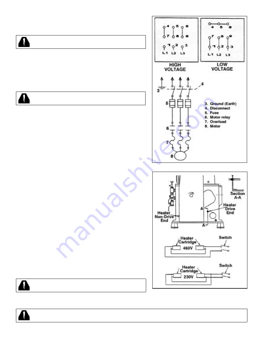
For installations requiring starting at ambient temperatures lower than
60°F (16°C), electric heaters should be installed in the water jacket. See
Figure 4.
WARNING: Do not allow the cooling water to freeze in the
pump.
Freezing of the cooling water jacket usually results in extensive damage to
the pump cylinder which cannot be repaired.
Locate the water inlet and outlet connections which are labelled on the
pump. Connect a water supply line with “on-off” valve to the water inlet,
and an open drain to the water outlet. The inlet line should have a flow
regulating valve. If the water supply is unreliable, it is advisable to install
a flow switch to stop the pump or signal when the flow is interrupted.
Normally the cooling water will be off when the pump is not running.
A water pressure relief valve (item 44 of the parts list) is fitted in the water
jacket. This relief valve is set to open at 50 PSIG (3.5 bar). Standard cooling
water rates are for up to 80°F (26°C) supply temperature and operation
within the design continuous operating pressure range of .1 to 100 mm
Hga. Sustained operation above 100 torr (130 mbar) and/or long pump
downs generally require larger cooling water flow rate and/or external oil
heat exchanger. Larger cooling water rate increases cooling efficiency
reduces heat dissipation to room and keeps oil cooler (longer oil life and
less oil loss through the oil mist eliminator).
FILLING THE PUMP WITH OIL
For initial oil filling and the first filling after the pump has been disassembled,
the quantity of oil to be placed in the reservoir is one gallon less than
shown in the specifications. One gallon is required in the suction port
as outlined in “INSTALLATION, MANIFOLDING”. Use oil recommended
by Tuthill Vacuum & Blower Systems and see the specifications for the
quantity of oil required to fill the pump. Remove the filler plug at the top
of the separator housing and add oil until the level reaches the top of the
sight gauge. The level will drop to below mid-center of the gauge once
the pump is operated at blank off and the oil is distributed. Add or drain
oil as necessary, to keep the oil level at blank off 3/8 inch (1 cm) up from
the bottom of the glass. The oil level changes with operating pressure,
reaching the lowest level at blank-off.
CAUTION: Do not overfill the pump.
ELECTRICAL CONNECTIONS
WARNING: Disconnect pump from source of electrical power prior to making repairs or adjustments to any electric
component of the unit.
Figure 3. Typical Wiring Diagram
Figure 4. Heater Installation