background image

16

FPW Collector Installation Manual

In-roof Mounting

6

1

22

24

6

1

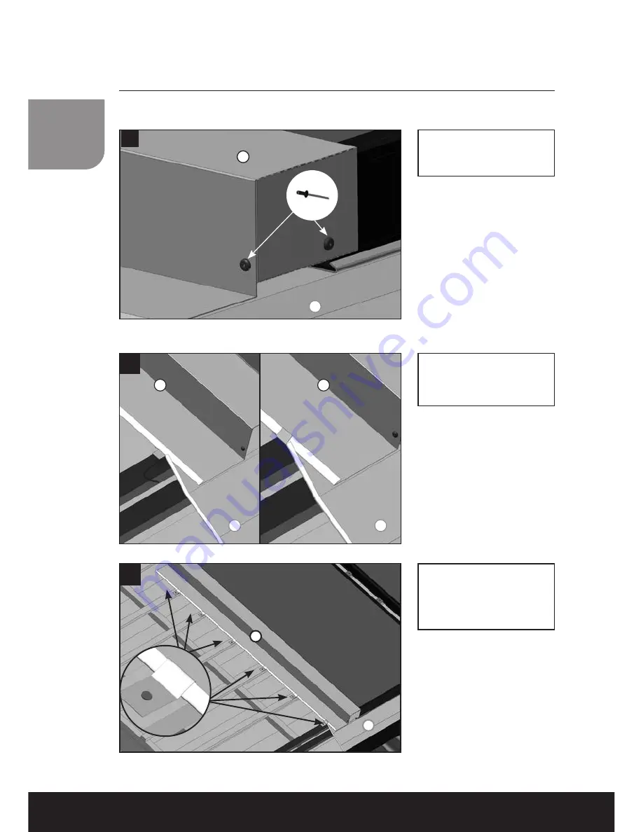
Fix the left sidepart 

with a fixation clip and 

a nail on 

EVERY

 roof 

batten.

6

1

6

1

23

Bend the flap on the 

left frontpart over the 

left sidepart.

Fix the bent flaps with 

2 rivets.

Summary of Contents for FPW18

Page 1: ...SolarThermalEnergy T 44 0 28 3836 4520 www kingspanthermomax com FPW FLAT PLATE INSTALLATION MANUAL...

Page 2: ...ion guidance 29 Pipework 1st fix 30 Standard pipework connections 31 Dual Collector Installation 32 Pump Station 33 Safety Vessel Connections 34 Wiring the Solar Control Panel 35 Maintenance Commissio...

Page 3: ...t use sharp objects to open the tube boxes Installation Guidance Unpack and install tubes and flat plates only after the manifold and pipe work has been installed With the HP400 and HP450 only tubes m...

Page 4: ...orptance 95 95 95 Emittance 4 4 4 Welding Method Laser Welding Heat Carrier Volume ltr 1 1 07 1 27 Number of Riser Tubes 9 10 12 Tube pitch mm 110 110 110 Glass Material Low Iron Tempered Glass Transm...

Page 5: ...stant to 150 C and the aging effect of the sun Silicone is applied between the EPDM and glass Regular rain cleans the glass In locations with low rainfall the glass must be cleaned It can be cleaned b...

Page 6: ...FPW Collector Installation Manual Mounting the Panel Flat Roof A Frame Kit FPW18 SINGLE KFP0024 FPW18 DOUBLE KFP0025 FPW21 SINGLE KFP0014 FPW21 DOUBLE KFP0015 FPW25 SINGLE KFP0049 FPW25 DOUBLE KFP005...

Page 7: ...05 On roof Bracket Kit Mounting the Panel Flat Roof FPW18 SINGLE KFP0026 FPW18 DOUBLE KFP0069 FPW21 SINGLE KFP0016 FPW21 DOUBLE KFP0068 FPW25 SINGLE KFP0072 FPW25 DOUBLE KFP0073...

Page 8: ...PW Collector Installation Manual Mounting the Panel Flat Roof On roof Bolt Kit FPW18 SINGLE KFP0215 FPW18 DOUBLE KFP0201 FPW21 SINGLE KFP0202 FPW21 DOUBLE KFP0203 FPW25 SINGLE KFP0204 FPW25 DOUBLE KFP...

Page 9: ...00 mm 220 mm collectors edge Before mounting the cassettes please check the dimensions above Add the dimensions of the cassettes to the collector dimensions using the table below Individual Collector...

Page 10: ...ation bracket 5 Double fixation bracket 6 left sidepart 7 right sidepart 8 connectionpart 9 supporting plate 10 left backpart 11 centre backpart 12 right backpart 13 backpart connection 14 Left frontp...

Page 11: ...ttens as shown in pict no 2 Start the mounting with the left frontpart Just hook it on the roof batten and fix it with 4 sealing screws pict 3 4 3 1 Marking for roof tiles 1 2 3 14 15 16 In roof Mount...

Page 12: ...e the center frontpart on the roof batten like the left one and plug it together with the left frontpart until it fits to the marked line on the left frontpart pict 6 Then fix it with 4 sealing screws...

Page 13: ...the right frontpart on the roof batten like the left and center one and plug it together with the center left in the case of only 2 collectors frontpart until it fits to the marked line on the center...

Page 14: ...ollector Installation Manual 10 After the frontparts are mounted the next step is to place the collectors pict 10 12 For details of the pipe connections see pages 30 32 12 11 1 1 2 3 14 15 16 In roof...

Page 15: ...on the outer side with a single fixation bracket on EVERY roofbatten 14 5 Place a double fixation bracket on EVERY roof batten between the collectors 5 4 Place a single fixation bracket on EVERY roof...

Page 16: ...Collector Installation Manual In roof Mounting Place a 100 mm foam gasket as shown in pict 18 and 19 6 17a 100 mm 16 6 1 17 6 1 1 6 18 6 1 Fit the left sidepart to the collector as shown in pict 17 a...

Page 17: ...15 In roof Mounting 19 1 6 20 6 1 6 1 6 1 6 1 21 Bend the flaps on the left sidepart as shown in pict 20 21...

Page 18: ...lation Manual In roof Mounting 6 1 22 24 6 1 Fix the left sidepart with a fixation clip and a nail on EVERY roof batten 6 1 6 1 23 Bend the flap on the left frontpart over the left sidepart Fix the be...

Page 19: ...17 In roof Mounting 27 8 8 25 26 7 3 8 8 6 7 8 2 8 27a Place the connection parts as shown in pict 26 27 and 27a Mount the right sidepart following the same procedure as for the left pict 16 24...

Page 20: ...Collector Installation Manual In roof Mounting 8 8 28 100 mm 29 8 8 30 Bend the flaps on the lower side of the connection part as shown in pict 30 and 31 Place a 100 mm foam gasket as shown in pict 28...

Page 21: ...19 In roof Mounting 33 8 8 32 8 Fix the bent flaps with 2 rivets 31 8 8...

Page 22: ...al 490 mm 340 mm For the fixation of the supporting plates and the backparts place additional roof battens as shown in pict no 34 and 35 Place the supporting plates as shown in pict 36 37 and 37a 36 9...

Page 23: ...8 39a 8 9 Fix every supporting plate with 2 nails on the roof batten In roof Mounting Bend the flap on the upper side of the connection part along the perforation that it fits to the hole on the supp...

Page 24: ...22 FPW Collector Installation Manual 42 10 11 12 41 6 8 10 40 10 6 In roof Mounting Fit the left backpart to the collector and into the left sidepart Pict 41 and 42...

Page 25: ...er backpart with 2 sealing screws on the roof batten Fit the center backpart to the collectors profile as shown in pict 42 In the case of only 2 collectors please continue with the right backpart pict...

Page 26: ...right backpart to the collector and into the right sidepart Pict 47 and 42 Fix the right backpart with 2 sealing screws on the roof batten Place the backpart connection as shown in pict 49 46 12 11 8...

Page 27: ...ry backpart connection Place the backpart connection as shown in pict 50 so that the holes fit to the holes in the supporting plate Then fix the backpart connection with 1 pcs sealing screw on the roo...

Page 28: ...ight backpart with 2 fixation clips and nails on the roof batten and with 1 rivet pict 52 and 53 54 4 5 mm 52 10 6 4 5 mm 12 7 53 In roof Mounting Form the left and the right frontpart at the corners...

Page 29: ...own in pict 55 Foam gaskets are only needed for pan tile cassettes 56 1 2 3 In roof Mounting Finally form the aluminium apron to the contures of the roof tiles as shown in pict 56 and fix it with the...

Page 30: ...ght backpart 13 Backpart connection 14 Left frontpart flat tiles 15 Center frontpart flat tiles 16 Right frontpart flat tiles 1 Left frontpart pan tiles 2 Center frontpart pan tiles 3 Right frontpart...

Page 31: ...mmended to connect the manifold through the building fabric and allow flexibility in connecting to the internal pipe work Flexible stainless steel pipe kits are available with a range of lengths and f...

Page 32: ...30 FPW Collector Installation Manual Connecting 1st fix part number KSK0032 1 ISO228Rp 3 4 to G 3 4 2 3 4 washers 3 DN16 hose 2m preassembled 4 3 4 stop ends 6 PT1000 sensor 11 Sensor retaining cap...

Page 33: ...31 Flat Plate Connection Kit KFP0067 1 ISO228Rp 3 4 to G 3 4 2 3 4 washers 3 Stop end...

Page 34: ...pipe should then be connected to the opposite upper collector port either right or left depending on the return pipe connection The 2 remaining ports that are not in use should be capped An installati...

Page 35: ...for systems up to 12m2 Pump Station Key 1 Drain connection 2 Fill connection 3 Flow meter 4 Isolating valve 5 Motorised pump 6 6 bar pressure relief valve 7 Expansion vessel connection 8 Pressure gau...

Page 36: ...ansion vessel supplied includes an appropriate corrugated hose and threaded connection to join the vessel to the pump station Temperature Reducing Vessel TRV Also known as a cooling vessel or stratifi...

Page 37: ...100 mm from insulated pipes which may become hot during operation Control panels use PT1000 sensors containing twin core copper cable with a 0 75mm cross section The sensors supplied are 1 5 metres in...

Page 38: ...otective earth for power connection terminal block 3 Signals terminal block 1 4 4 x sensor input Pt1000 temperature sensor 5 1 x sensor input Pt1000 temperature sensor or pulse water meter input RS 1...

Page 39: ...the Solar Antifreeze Fluid for approximately 30 minutes For East West systems flush and fill each collector for approx 30 minutes 5 Open and close the isolating valve intermittently to circulate air b...

Page 40: ...flow rate is achieved 3 Stop the pump Setting the flow rate Isolating valve Left side view of controller OPEN CLOSED The Solar Antifreeze Fluid we supply with our solar systems is a thermal transfer...

Page 41: ...g the maintenance schedule overleaf In addition the user should check the system pressure at regular intervals A visual inspection of the pressure gauge is required to check that the system pressure i...

Page 42: ...re filling System pressure Expansion vessel setting after filling Flow rate Antifreeze level pH reading Inspection of barium getter vacuum tubes only Engineer details Print name Sign Telephone No Upon...

Page 43: ...t Guidance for the Republic of Ireland Note Varisol Collectors are not NSAI agrement compliant Solar installations in the Republic of Ireland must be installed in accordance with the Irish Agr ment Bo...

Page 44: ...lations Please see Construction of Collector section for details of materials used in the construction of Kingspan collectors 1 Electrical Isolate controller from mains Remove cables to consumer units...

Page 45: ...the Company s liability shall be limited to the excess if any of the cost to the Buyer in the cheapest available market of similar goods to replace those not delivered over the Price of the Goods 4 T...

Page 46: ......

Page 47: ......

Page 48: ...the specification as shown in this literature REF B10342B Flat Plate Manual ENG JAN 17 This brochure is printed on environmentally friendly paper Kingspan Environmental Ltd 180 Gilford Road Portadown...

Reviews: