PA G E 4
P R O G R A M M I N G M A N UA L
K L A - 1 1 0
2.0 PROGRAMMING THE SYSTEM VIA
ETHERNET CONNECTION
Once the rack has been mounted and all the modules installed
and connected, the next step is to locate each module so that
the software image mimicks the physical layout. After you have
gained access to the system by using the password, you will see
all modules displayed on your computer. Each module (KCC110/
KVM110) factory default location setting is -1, initially all the
modules in the software will be on the left hand side of the KLA-
110 (The KLA-110 will be on the far right hand side). .
In the headend software, click on
‘Locate’ at the bottom of a module. On
your computer display screen the green
bar at the top of the channel will flash.
Now physically look at the modules
when clicking ‘Locate’.
A Green LED on front of one of the modules will flash. Count
the module position as it is depicted in the drawing (Fig.1). Now
click on ‘Settings’ at the bottom of that module. This will open a
window where the settings can be changed. At this stage, change
the field that says ‘Module Position’ to the position it is phsyically.
NOTE:
Module positions allowed are -5, -4, -3, -2, -1, or 1, 2, 3, 4,
5 depending on what side they are positioned on the KLA-110 launch
amplifier as shown in Fig.1.
Module Positions
-5 -4 -3 -2 -1
1 2 3 4 5
When you have changed the modules position, click on ‘write’
to save the information. Repeat these steps until all modules are
in their correct physical position. The system displayed on your
computer will replicate the number, position and type of modules
installed.
To change other settings such as channel name, input frequency,
output frequency, RF output level, bandwidth and mode, see
KCC110, or KVM110, and KLA110 Parameters.
2.1 KCC-110 PARAMETERS
In the KCC110 settings, you can change the
Module Name, Module Position, Channel Name,
Input frequency, Output Frequency, RF Output
Level, RF Output and Mode. In addition you can
monitor the output level.
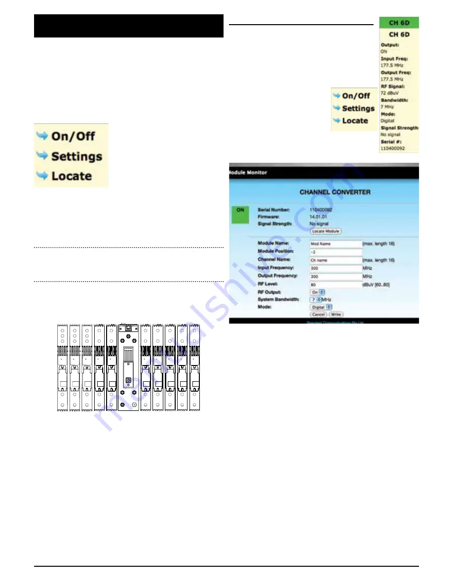
To change these settings, click
on ‘settings’ at the bottom of the
appropriate module as displayed
on your computer screen. The
following window will appear.
The following parameters can be adjusted using the software.
Module Name:
Text can be added to name the module.
Module Position:
This is the actual module position in the
rack - position numbers that can be used
are -5, -4, -3, -2, -1, 1, 2, 3, 4, 5.
Channel Name:
Text can be added to name the channel.
RF Output:
You can switch the RF output ON or OFF
Input Frequency:
Enter the frequency of the channel being
received - adjustable in 125 KHz steps
Output Frequency:
Enter the frequency of the channel being
transmitted - adjustable in 125 KHz steps
RF Level:
You can adjust the output level from 60 -
80dBuV
System Bandwidth:
This is the bandwidth of the channel
being received - 7 or 8 MHz
Mode:
This is used for the type of transmission
that is being processed or converted -
analogue or digital.
Once changes have been made, click ‘Write’ and the new settings
will be saved in memory.
FIG. 1


