background image

USSC 

13

12 

USSC

ON

OFF

Auger

Delay

Mode

Auto

Manual

Heat

Range

Room

Fan

Draft

Fan

Aux.

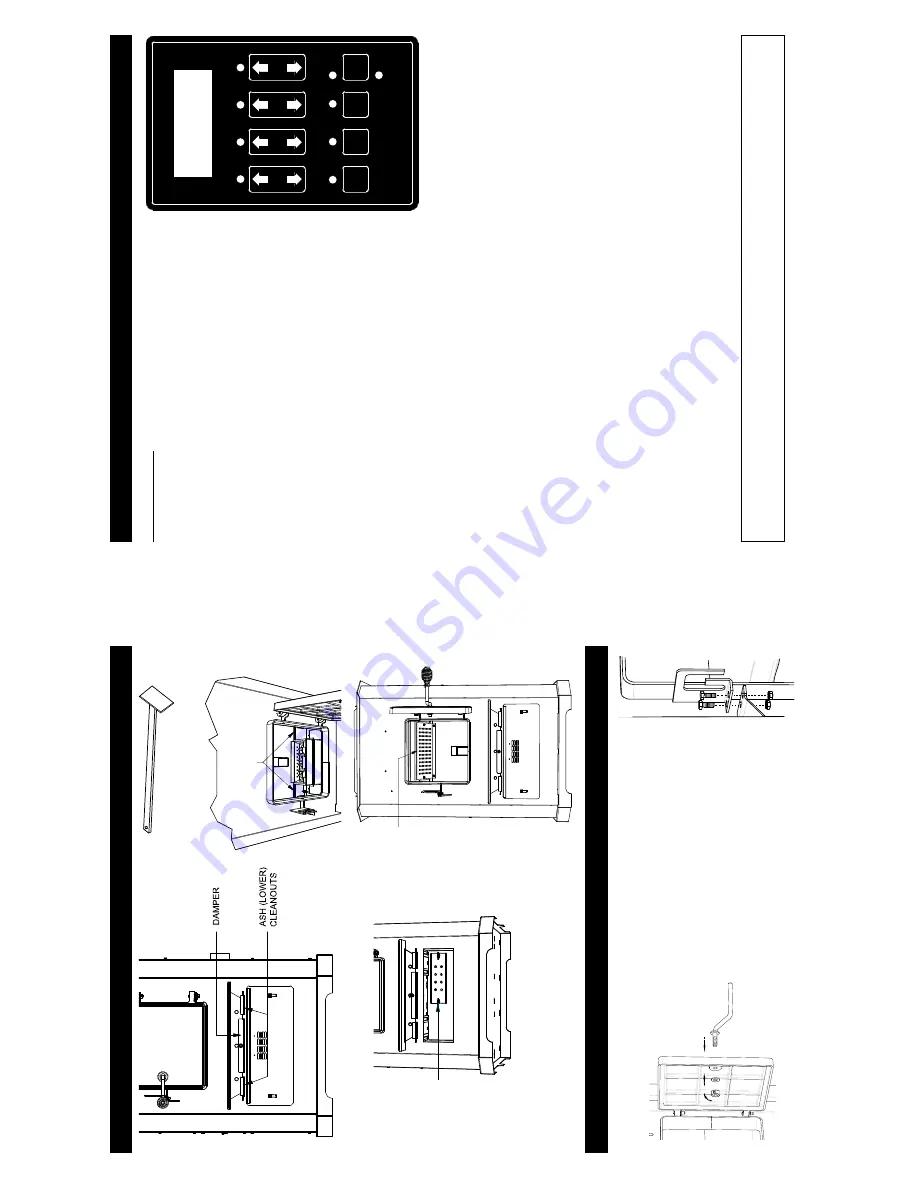
CONTROL

 P

ANEL

T

urning the furnace OFF/ON, as well as adjustments for the fuel feed rate 

and room fan speed are performed by pressing the appropriate button(s) 

on the control panel which is located on the lower left-hand side of your 

King

 furnace.

This unit can operate in either automatic or manual mode.  

Automatic mode 

has pre-set default settings.

Pressing the 

“ON” 

button on the control panel will begin the start-up


sequence for the furnace.  Fuel will begin to feed through the auger feed 


`

Z

=?

<

the auger continuously until button is released, which feeds additional fuel.

Pressing the 

“OFF” 

button on the control panel will cause the furnace to 

enter its shut-down sequence.  

The fuel feed system will stop pulling fuel 


!


!

the fans will stop running.

Pressing the 

“Heat Range”

 arrows, up or down, will adjust the amount of 

fuel being delivered to the burnpot.

This unit comes preset from the factory to burn shelled corn.  

The display 

=

Cr

” in front of the heat setting.  If burning only wood pellets, this 

setting must be changed.  

T

o

 change, press and hold the heat range up and 

down buttons simultaneously for approximately 2-3 seconds.  

The display 


=

Cr

?

=

Pr

”.  If burning a pellet(50%) and corn(50%) mix, 

=

Cr

” setting will work the best for optimum performance.  

  ‡ˆ=?<

 X

in accordance to the heat range setting.  However

, this speed can be manually operated by pressing the 

“Draft Fan” 

=

>?

!

= ‚J?!

Z

to adjust fan speed.  When the furnace is in the manual mode, the optional thermostat  will not properly control the unit. 


When adjusting the Draft Fan setting, try only 1 setting above or below the heat setting.

The room fan(s) will come on once the unit has reached operating temperature.  

The room fans will automatically adjust 

their speed in accordance with the heat range setting.  By pressing the 

“Room Fan”

<!

= ‚

A” which is automatic or how many fans are running.

The 

z={

<

 J

\

=>>?!

=J?

for easy removal for cleaning.  

The agitator

, when in 

Automatic mode, will operate at set intervals.  However

, these can 

<<=J?<

<X ‹‘!=‹? 


=‘?

The 

“Auger Delay”

 button can be used to pause rotation of the 

Auger and 

Agitator for approx. 1 minute.  

This can be 

<=?<

The 

“Mode” 

button is used to switch between manual and automatic mode.  When in auto mode, the fans, auger

, and 

agitator will operate at preset intervals unless changed manually using the buttons mentioned above.  When in manual 

mode, the draft fan (exhaust) will operate at full speed (100%), so the air must be controlled with the damper just below 

the viewing door

.

During normal operation, this unit constantly monitors itself for potential problems. In the event of an error condition, the 

unit will stop and an error code will be shown in the display

.  See the list of error codes found at the end of this manual.

Opera

tio

n

C

om

p

on

en

t L

o

ca

tio

n

EXH

AUS

T

C

L

EA

NOU

T

(locate

d

 b

ehind

th

e a

s

h

 pan

)

AS

H CL

EAN

O

U

TS

STA

IN

L

E

SS STEEL

BAFFL

E

CLEANOUT

 T

OOL

^/q

/^

;

>@


#


 6

+

;

>@

$$


#

 |


  +

/>?"@


"_>

<


chimneys REGULARL

Y

.

W

ARNING

D

o

or

 H

andle a

n

d F

u

el L

at

ch

 A

ss

em

b

ly

Insert door handle into door

. From rear side of door

place a 1/2” washer over the threaded part of the handle, 

then attach the lock nut.  

T

ighten the nut, then back of

1/4 turn to allow free operation of the handle.

With two 1/4-20 x 3/4 hex bolts, at-

tach the door latch to the door latch 

mounting bracket on the left side of 

the door frame as illustrated. 

The slot 

in the bracket and latch are for door 

seal adjustment. Make the proper ad-

justments, then tighten the nuts. 

The 

door

’s

 gasket should be snug against 

the door frame on the furnace. 

(1) Door Handle

(1) 1/2” W

asher

(1) 1/2” Lock Nut

(1) Feed Door Latch

(2) 1/4-20 x 3/4 Hex Bolt

‡Œˆ^[†‚Œ‹&

Summary of Contents for 8500

Page 1: ...E 800 750 2723 FAX 423 837 2109 UNITED STATES STOVE COMPANY Keeping North America Warm Since 1869 MULTI FUEL FURNACE MODEL 8500 Report 215 S 22b 2 TESTED LISTED BY PORTLAND OREGON USA Part No 851976 Safety tested and listed to UL 391 2010 ASTM E1509 04 and CSA B366 1 11 C residential or mobile home as a stand alone or add on furnace ductwork connection only Approved for US and Canadian use French ...

Page 2: ...ype 8 Pellet Vent Installation 8 Pellet Vent Termination 8 Vent Termination Clearances 9 Through the Wall Installation 10 Through the Roof Ceiling Installation 10 Primary and Secondary Furnace Illustrations 11 OPERATION 12 How Your Furnace Works 12 Damper Control Adjustment 12 Control Panel 13 Unit Preparation 14 Start Up Procedure 14 Shut Down Procedure 14 Daily Operation 15 Safety and Convenienc...

Page 3: ... the fuel supply Store your pellets in a dry place to prevent them from absorbing added moisture To decrease sawdust buildup the hopper will need to be vacuumed out after every 6 8 bags of pellets or more often if the pellets are poor quality You may have to screen sift each bag of pellets if sawdust becomes a problem Z _ _ with small to midsize pellets Low ash content pellets will allow you to bu...

Page 4: ...g cut down on operation time Ì Installation IMPROPER INSTALLATION The manufacturer will not be held responsible for damage caused by the mal function of a furnace due to improper venting or installation Call 800 750 2723 and or consult a professional installer if you have any questions FLOOR PROTECTION K non combustible surface should be large enough to extend a minimum of 6 inches in front 6 inch...

Page 5: ...al vent MUST NOT exceed 4 feet this does not include the clean out tee Use no more than 180 degrees of elbows two 90 degree elbows or two 45 degree and one 90 degree elbow etc to maintain adequate draft PELLET VENT TYPE J K Z connector provided on the back of the furnace use a 3 inch to 4 inch adapter for 4 inch pipe Use 4 inch vent if the vent height is over 12 feet or if the installation is over...

Page 6: ...ut section and vertical pipe inside until ground level is reached With this installation you have to be aware of the snowdrift line dead grass and leaves We recommend a 3 foot minimum vertical rise on the inside or outside of the house deck in an alcove under a window or between two windows We recommend Simpson Dura Vent or Metal Fab kits THROUGH THE ROOF CEILING INSTALLATION When venting the furn...

Page 7: ...the unit has reached operating temperature The room fans will automatically adjust their speed in accordance with the heat range setting By pressing the Room Fan A which is automatic or how many fans are running The z J J for easy removal for cleaning The agitator when in Automatic mode will operate at set intervals However these can J X The Auger Delay button can be used to pause rotation of the ...

Page 8: ...spected and cleaned at least monthly during the burning season Be aware less creosote is deposited and that weekly cleaning can be necessary in mild weather even though monthly cleanings can be enough in the coldest months Check the clean out tees periodically to determine the required cleaning schedule 3 or 4 inch chimney brushes are available for chimney cleaning If the exhaust system or outside...

Page 9: ...e backside of the cleanouts on the front of the unit If gaskets become torn or damaged they must be replaced FAN MOTORS Clean the air holes on the motors of both the draft fan and room air fans annually Remove the draft fan from the exhaust duct and clean out the internal fan blades as part of your fall start up A new gasket may be purchased from United States Stove s Parts Department PAINTED SURF...

Page 10: ...ition Duct 10 Round 1 34 891331 Spring Handle Brushed Nickel 1 35 891364 Hearth Plate 1 36 891374 Access Panel Plenum 1 37 891423 Pin Door Hinge 2 38 891445 Ash Pan Assembly 1 39 891455 Weldment Burnpot 1 40 891461 Cover Exhaust Cleanout 1 41 891471 Lid Weldment 1 42 891440 Cleanout Ash 2 43 891262 1 44 891457 Cleanout Ash Lower 2 45 891485 Weldment Damper 1 46 89586 Auger Nipple 1 47 80501 Thermi...

Page 11: ...tion air Fuel has too much moisture Viewing window becoming black shortly after start up Adjust the air damper to a more open position Use a fuel with less moisture content PROBLEM CAUSE Not enough combustion air Fuel has too much moisture Z chamber Adjust the air damper to a more open position Use a fuel with less moisture content Stove might be cycling excessively due to temperature cut backs Re...

Page 12: ...ce of Purchase Retailer ______________________________________________________ City____________________________________________ State_______ Zip_________________ If internet purchase please list website address___________________________________ Date of Purchase _______________________________________________________________ Reason for Purchase Alternative Heat Main Heat Source Decoration Cost Oth...

Page 13: ...24 USSC CUT HERE CUT HERE Fold Here Fold Here United States Stove Company P O Box 151 South Pittsburg TN 37380 Fold Here PLACE STAMP HERE ...

Reviews: