Vehicle Starting and Driving
4-2
2 Check level of the coolant
The coolant level is automatically monitored.
If coolant level gets too low
,
the digital indicator
displays a driver information on the combination
instrument. In this case, park vehicle in a safe place as
traffic conditions permit, stop engine and visually
check the coolant level.
Check the coolant level only when the engine doesn’t
work and its temperature is below 50
℃
.
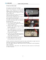
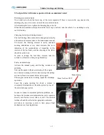
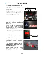
The anti-freezing rust-inhibiting engine coolant level
can be observed from the observe pipe.
The coolant level should be between the maximum
level (MAX.) and minimum (MIN.) level indicators in
the compensation tank.
If it is necessary to add coolant to the system:
a.
Place the heating system command in the position
of maximum heating potency.
b.
Add the coolant to the system up until the
maximum level indication. Only use coolant
which is recommended.
c.
The compensation tank cover should not be
opened when temperature of the coolant is still
high to avoid being scalded Place the lid on the
system and turn it to the limit.
d.
Pressure valve of the compensation tank should be
opened when adding the coolant to eliminate air in
coolant pipeline of the diesel engine.
e.
Run the engine for a short time at varied rotations.
f.
Stop the engine and check the coolant level.
If necessary add more coolant to the system
Anti-freeze and antirust solution (mixture of glycol and water) should be added to cooling system from
time to time to avoid sediment, frost, oxidation and increase boiling point.
Note: When adding coolant, please choose the same model to avoid sediment. If coolant is degenerative,
replace it immediately.
Coolant specification as shown below: users should choose products produced by normal factories
according to requirement
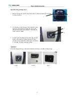
Observe pipe
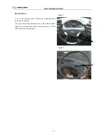
Observe pipe
Summary of Contents for XMQ6900 Series
Page 19: ...Operation Instruction 3 1 Figure 17 Set MotPPR Figure 18 Clear Trip A Figure 19 Clear Trip B...
Page 31: ...Operation Instruction 3 3 CC350 355 series A C Operation...
Page 32: ...Operation Instruction 3 3...
Page 33: ...Operation Instruction 3 3...
Page 34: ...Operation Instruction 3 3...
Page 35: ...Operation Instruction 3 3...
Page 44: ...Operation Instruction 3 4 1 9 Retarder operation...
Page 45: ...Operation Instruction 3 4 Section 1 1 2 1 10 Stopping parking...
Page 49: ...Operation Instruction 3 4 1 14 1 Emergency operation...
Page 50: ...Operation Instruction 3 5 WABCO ABS BASIC INTRODUCTION...
Page 51: ...Operation Instruction 3 5...
Page 52: ...Operation Instruction 3 5...
Page 53: ...Operation Instruction 3 5...
Page 54: ...Operation Instruction 3 5...
Page 55: ...Operation Instruction 3 6 ECAS System Introduction for tourist bus use 1 System introduction...
Page 56: ...Operation Instruction 3 6 3 System function...
Page 57: ...Operation Instruction 3 6...
Page 169: ...Appendix 7 6 Air braking schematic diagram...
Page 170: ...Appendix 7 7 Electric schematic diagram of the complete car 1...
Page 171: ...Appendix 7 7 Electric schematic diagram of the complete car 2...
Page 172: ...Appendix 7 7 Electric schematic diagram of the complete car 3...
Page 173: ...Appendix 7 7 Electric schematic diagram of the complete car 4...

