INSTALLING FRONT RAIL AND TUBE ASSEMBLY
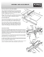
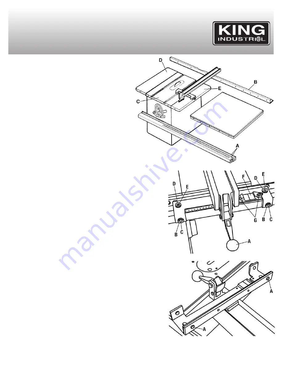
Place and align the mounting holes of the front rail and tube
assembly (A) Fig.1 with the holes in the front lip of the table (C) and
extension wings (D & E). Install the front rail and tube assembly to
the table and extension wings using 4 countersunk head bolts, 8
washers, 4 spring washers and 4 hex. nuts.
Before securing it in place, adjust it up or down to ensure the front
rail edge is set at 1/8” below the lowest edge of the miter gauge
T-slot. Once adjusted, tighten all 4 countersunk head bolts.
INSTALLING REAR RAIL
Place and align the mounting holes of the rear rail (B) Fig.1 with the
holes in the rear lip of the table (C) and extension wings (D & E).
Install the rear rail to the table using 2 hex. bolts and 2 washers.
Then 2 use hex. bolts, 4 washers, 2 spring washers and 2 hex.
nuts to fix the rear rail to the extension wings. Before securing it in
place, adjust it up or down to ensure the rear rail edge is set flush
with the lowest edge of the miter gauge T-slot (to allow free
movement of the miter gauge). Once adjusted, tighten all 4 bolts.
ADJUSTING RIP FENCE
The rip fence must be perfectly aligned with the table T-slot, to verify this, place rip
fence on table and align the edge of the rip fence with the table T-slot, lower the
locking lever (A) Fig.2 to lock it into place. Check to see if the edge of the rip fence
and the table T-slot are parallel. If they are not parallel, unlock the rip fence and turn
it upside down as shown in Fig.3. Adjust the set screws (A) Fig.3 in or out, verify your
adjustment, repeat if necessary.
The lock lever pressure can be adjusted by loosening the front lock nuts (B) Fig.2
and adjusting the set screws (C) the same amount, make sure the fence remains
parallel with the table T-slot. Retighten lock nuts.
To set the fence perpendicular to the table, place a square on the table and against
the side of the fence, loosen the top lock nuts (D) and adjust the set screws (E) until
the fence is perpendicular. Retighten lock nuts.
The pointer window (F) Fig.2 position can be adjusted if needed, loosen pan head
screws (G), reposition the pointer window and retighten pan head screws.
ASSEMBLY AND ADJUSTMENTS
FIGURE 1
FIGURE 2
FIGURE 3

