


ADJUSTMENTS & OPERATION
USING AND ADJUSTING TAbLE ROLLERS continued...
If an adjustment is necessary:
4. Loosen the hex. nut (B) Fig.9 located underneath the table below the infeed roller
(A).
Note:
It will be necessary to raise the table in order to gain access to the the hex. nut.
5. Rotate the hex. nuts (C) as required to raise or lower the height of the infeed
roller.
6. Reverify the adjustment (steps 2-3), once correctly adjusted retighten hex. nut
(B).
7. Repeat steps 2-6 for the opposite side of the infeed table roller.
8. Repeat steps 2-6 for both sides of the outfeed table roller.
ROTATING/CHANGING CUTTERHEAD CUTTER INSERTS
WARNING!
When checking cutter inserts, always make sure the Planer is
disconnected from the power source.
A variety of T20 Torx bit tools are supplied with this planer to remove or adjust the
position of the cutter inserts secured in the cutterhead. The spiral cutterhead is
equipped with 180 indexable cutter inserts (14mm x 14mm x 2mm accessory model
KW-140) which can be rotated to reveal one of its four cutting edges. Once a cutter
insert becomes dull or damaged, simply rotate it 90° to reveal a fresh cutting
edge. In addition, each edge of the cutter inserts is marked with a number. These
reference numbers can be used as an indicator of which edges are used and which
are new. Once the reference mark revolves back around to its starting position, the
cutter insert should be replaced.
To check, adjust or replace the cutterhead cutter inserts:
1. Open the top cover (A) Fig.2.
2. Note the position of the reference number (A) Fig.10 on each cutter insert (B).
Using the T20 Torx bit tool (C), loosen and remove cutter insert screw (D) by
turning counterclockwise.
Note:
The cutter insert and the seat should be as clean as possible. This will prevent
breakage of inserts and ensure proper insert alignment.
3. If cutter insert is damaged, replace it with a new one. If it is not damaged, rotate
it as shown in the illustration in Fig.11.
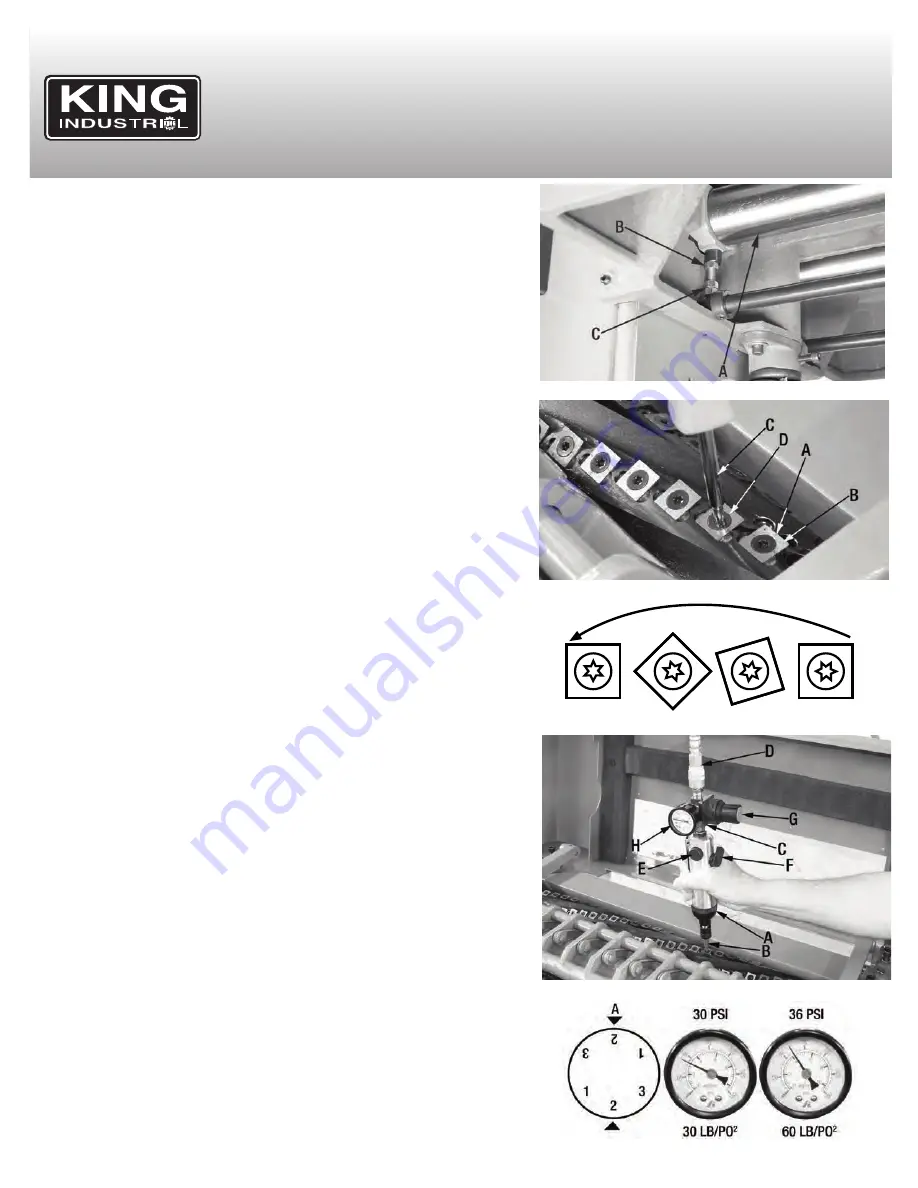
A 1/4” air screwdriver and regulator (3/8” NPT fittings) is supplied with this Planer,
they should be used to properly torque the cutter inserts. To torque the cutterhead
cutter inserts:
1. Set up the supplied 1/4” air screwdriver (A) Fig.12. Install a T20 Torx bit (B) into
the air tool, install the regulator (C) with pressure gauge (H) to the air tool, use
Teflon tape on the threads to avoid air leaks.
2. Connect a hose having a 1/4” female quick connect fitting (D) to the 1/4” male
fitting of the regulator (C).
3. Set the RPM dial (E) Fig.12, as shown in (A) Fig.12A .
4. Set the rotation direction of the air tool by adjusting the lever (F) for clockwise (R)
or counterclockwise (L) direction.
5. Once the air tool is set-up, turn the compressor on. Now the tool pressure rating
must be set. Pull the regulator knob (G) and turn the knob to set the output
pressure on the pressure gauge. Set the pressure rating to 30 PSI, as shown in
Fig.12A. Once set push the regulator knob back in to lock the setting and torque
the cutter insert by pressing the lever on the air tool.
6. Once the cutter insert is torqued to 30 PSI, set the regulator pressure to 60 PSI
as shown in Fig.12A and torque the cutter insert a second time.
7. Lower the top cover and secure it using the cap screw removed previously.
FIGURE 9
FIGURE 10
1
2
3
4
1
2
3
4
1
2
3
4
1
2
3
4
FIGURE 11
FIGURE 12
FIGURE 12A


