


UNPACkING & ASSEMbLY
UNPACkING AND CLEANUP
WARNING!
TO REDUCE THE POTENTIAL FOR PERSONAL INJURY AND/OR DAMAGE TO THE MACHINE, BEFORE ASSEMBLING MAKE
SURE THE MACHINE IS TURNED OFF. DO NOT TURN ON THE MACHINE UNTIL INSTRUCTED TO DO SO AFTER ALL
ASSEMBLY STEPS IN THIS MANUAL HAVE BEEN COMPLETED.
To ensure maximum performance from your Planer, clean it properly and install it accurately before use. As soon as you receive the Planer, we
recommend you follow these procedures:
1. Before lifting machine, remove all bolts locking it to its shipping base.
2. Transport machine to location with a pallet truck, sling or dolly.
3. Remove the protective coating from the table, bed rolls, feed rolls, and loose items packed with the machine. Open the top cover to gain
access to the chipbreakers and cutterhead, and remove the protective coating, see instructions below.
4. The protective coating can be removed with a soft cloth moistened with kerosene.
5. After cleaning, cover the table surfaces with a layer of good quality paste wax.
NOTE:
Do not use acetone, gasoline, or lacquer thinner for this purpose.
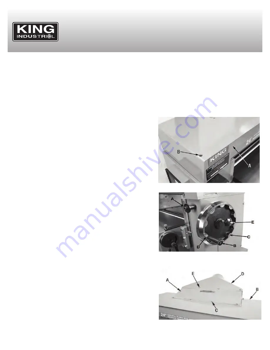
OPENING THE TOP COVER
1. The top cover (A) Fig.2 can be opened by loosening and removing the top cover
cap screw (B) located in the bottom left corner of the cover using a hex. key,
carefully lift the top cover.
2. Once the cleaning operation is finished, lower the top cover and replace the top
cover cap screw (B).
WARNING:
Sharp cutterhead exposed, wear protective gloves when cleaning.
MOVING PLANER
Remove the bolts that fasten the machine to the skid by opening up the access
panels at the bottom of either side of the machine.
1. The machine has two built in lifting anchors (A) Fig.3 that can be used to move
the machine using lifting straps and a forklift. One is located at the front of the
machine as shown, and the other is located at the rear on the opposite side.
2. Ensure that the lifting straps are attached to the lifting anchors, and nothing
else. Be sure that the machine is kept in a level position while lifting.
ASSEMbLY
INSTALLING HANDLE AND LOCk kNOb TO HANDWHEEL
1. Thread the handle (B) Fig.3 into the handwheel (C) and tighten the lock nut (D).
2. Thread the lock knob (E) Fig.3 into handwheel (C).
3. The table can be raised and lowered by loosening the lock knob (E), and
rotating the handwheel (C). Tighten the lock knob (E) to secure the table in the
current position.
INSTALLING CUTTERHEAD GUARD AND DUST CHUTE
To install the cutterhead guard:
1. Place the cutterhead guard (A) Fig.4 on the top cover (B) as shown, line up the
mounting holes.
2. Fasten the cutterhead guard using six hex. bolts and spring washers (C).
This machine is equipped with a dust chute with a 6” opening used for connecting
to a dust collector or dust collection system. Make sure the correct size fittings and
hoses are used to minimize airborne dust.
To install the dust chute:
1. Place the dust chute (D) Fig.4 on top of the cuttherhead guard (A) as shown.
2. Line up the holes, and fasten the dust chute to the cutterhead guard using four
hex. bolts and spring washers (E), then fasten the rear bottom section of the dust chute to the top cover using four more hex. bolts and
spring washers.
FIGURE 2
FIGURE 3
FIGURE 4


