ASSEMBLY
CAUTION: Follow all the assembly & installation instructions
completely before connecting the Wood Bandsaw to a power source.
STAND ASSEMBLY
NOTE: It is easier not to tighten the stand bolts until the belts and pulleys are
installed and aligned. Finger tighten only. This allows easy adjustment later.
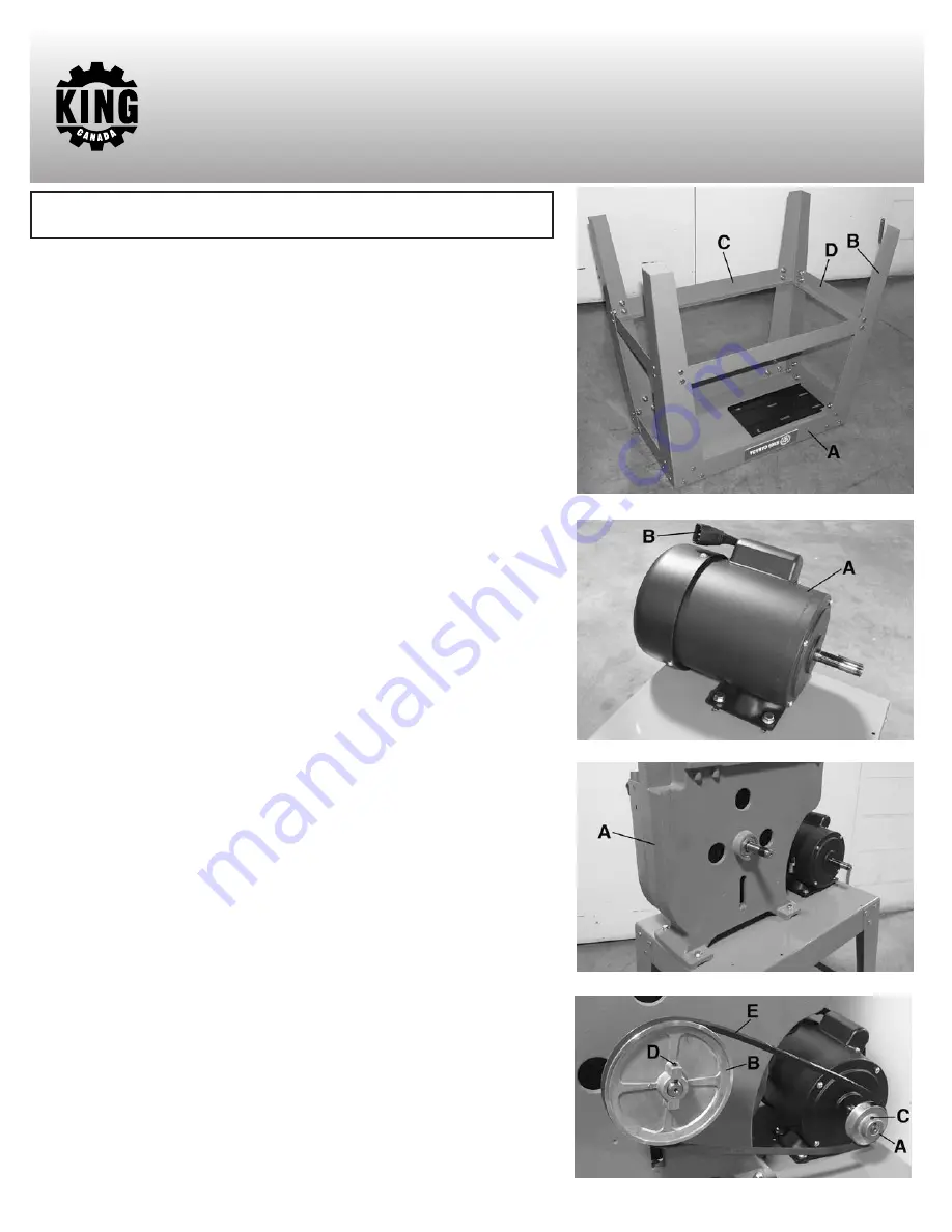
1. Locate the top of the stand (A) Fig.3 and the four legs (B). It is easier to assemble
the stand by placing the top upside-down on a bench or table. Using one carriage
bolt, a washer, lock washer and hex. nut for each hole, bolt the legs to the outside
corners of the top of the stand.
2. Assemble the four cross braces (C & D) to the inside of the legs of the stand. Again
use one carriage bolt, washer, lock washer and hex. nut for each hole.
3. Set the stand right side up on a flat surface, and finger tighten all bolts.
INSTALLING MOTOR ON STAND
When bolting the motor (A) Fig.4 to the top of the stand, the motor gets mounted to
the left side of the stand with its shaft facing the back as shown. Place four rubber
antivibration washers on the stand over the mounting holes and place motor on top
of them. Bolt the motor to the stand using short equal length hex. bolts, washers,
spring washers and hex. nuts. Do not fully tighten the hex. bolts at this point, to allow
for adjustment later. This motor comes with a quick connect plug (B) which connects
directly to the switch quick connct plug. This will facilitate unplugging the bandsaw.
INSTALLING THE BANDSAW FRAME ON STAND
The frame (A) Fig.5 of the bandsaw is mounted on the top of the stand with its drive
shaft facing the rear as shown. Align the four holes in the frame casting with the four
holes in the stand. A reinforcement bracket (stand diagram-part#5) should be
installed under the stand below the frame mounting holes using the frame fixing
hardware. Bolt the frame to the stand using hex. bolts, washers, spring washers and
hex. nuts. Do not fully tighten the hex. bolts at this point, to allow for adjustment later.
INSTALLING AND ALIGNING PULLEYS AND BELT
1. Remove the tape holding the key on the motor and frame drive shafts. Slide the
motor pulley (A) Fig.6 onto the motor shaft. Make sure the key sits in the shaft slot
under the pulley. Tap it into position, using a rubber hammer may be necessary.
Slide the drive pulley (B) Fig.6 onto the drive shaft. Make sure the key sits in the
shaft slot under the pulley.
2. Align the motor’s pulley and the drive pulley so that they are in a straight line. It
may be necessary to slide a pulley in or out on its shaft, and shift the frame and/or
the motor to align them in a straight line.
3. When the pulleys are in line, tighten the hex. bolts holding the frame to the stand
and the set screw (C & D) on each pulley.
4. Loop the belt (E) around both pulleys. Slide the motor away from the frame to
tension the belt. The belt is tensioned correctly when moderate pressure at the
midpoint between the two pulleys deflects the belt 1/2”. Tighten the hex. bolts that
hold the motor in place.
FIGURE 3
FIGURE 4
FIGURE 5
FIGURE 6


