background image

MAINTENANCE

All the ball bearings are sealed and lubricated for life and will require no
maintenance.

Cleaning

• After use, wipe off chips and dust adhering to the tool with cloth or the like.

Keep the blade guards and covers clean . Lubricate the sliding portions with
machine oil to prevent rust.

To maintain product SAFETY and RELIABILITY, repairs, any other
maintenance or adjustment should be performed by your nearest authorized
service center.

REPLACING CARBON BRUSHES

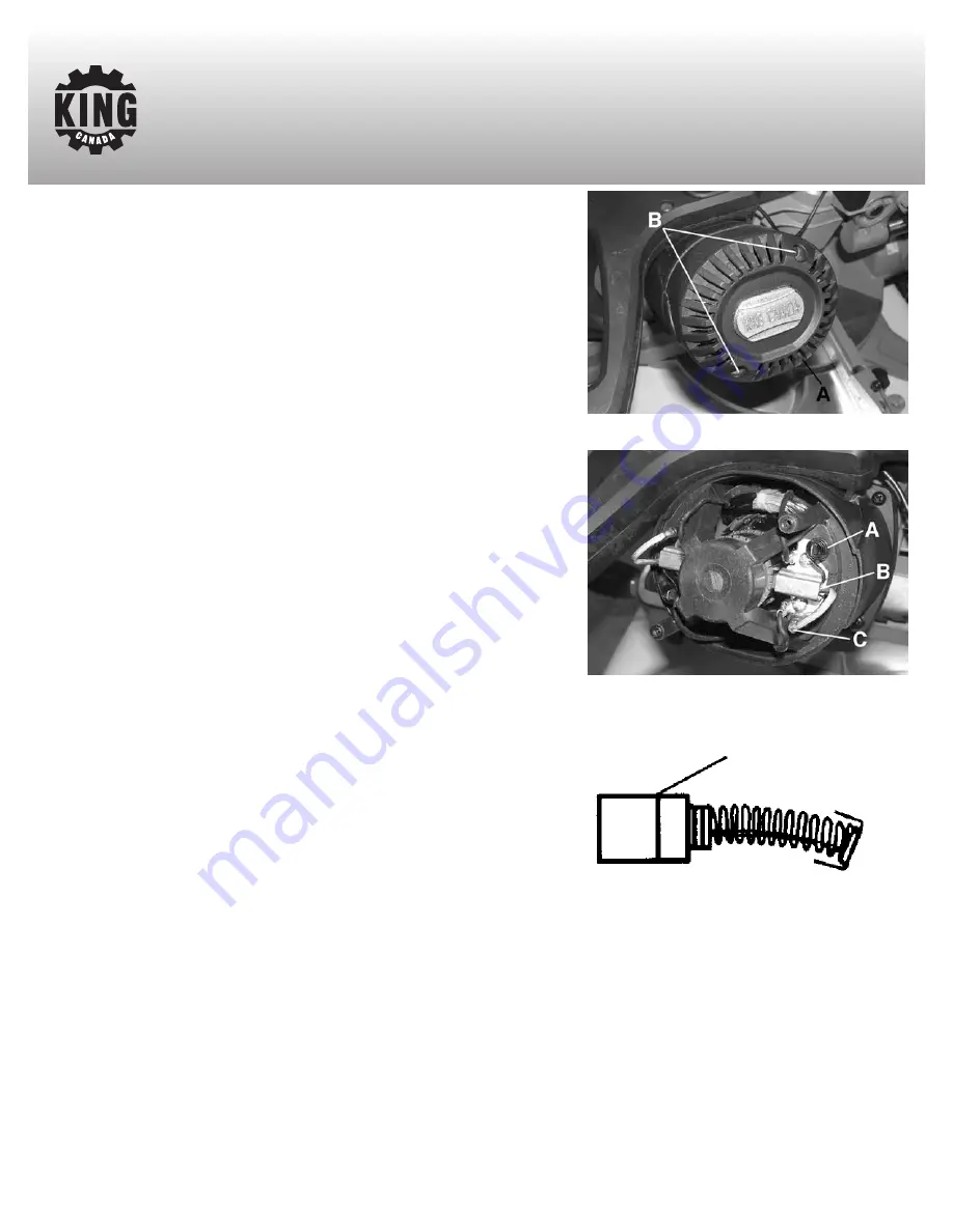
Remove and check the carbon brushes regularly (normally after 50 hours of
use). The carbon brushes are installed inside the motor housing. Using a
screwdriver,  remove the 2 pan head screws (B) Fig.21 that hold the motor
housing cap (A) in place.  

Once the motor housing cap is removed, to release the carbon brush (B) Fig.22
from the holder, lower the retaining spring (A). Disconnect the carbon brush
wire (C) from the terminal, remove the carbon brush from the motor housing
and inspect it. Repeat this step for the second carbon brush. Carbon brushes
need to be replaced once they wear down to the limit mark, see Fig.23. Keep
the carbon brushes clean and free to slip in the holders. 

If they have worn down to the limit mark, purchase a set of identical
replacement carbon brushes (both carbon brushes should be replaced at the
same time). Insert new carbon brushes into the holders, connect them to the
terminals, reposition the retaining spring and reinstall the motor housing cap
using the 2 pan head screws. 

Figure 21

Figure 23

Carbon brush limit mark

Figure 22

MAINTENANCE

Summary of Contents for 8385N

Page 1: ...KING CANADA 10 DUAL BEVEL SLIDING COMPOUND MITER SAW WITH TWIN LASER GUIDE INSTRUCTION MANUAL COPYRIGHT 2013 ALL RIGHTS RESERVED BY KING CANADA TOOLS INC MODEL 8385N Enhanced Twin Laser Effect 09 2013 ...

Page 2: ...enance King Canada shall in no event be liable for death injuries to persons or property or for incidental special or consequential damages arising from the use of our products To take advantage of this limited warranty return the product at your expense together with your dated proof of purshase to an authorized King Canada service center Contact your retailer or visit our web site at www kingcan...

Page 3: ...SE RIGHT TOOL Don t force the tool or the attachment to do a job for which it was not designed 11 WEAR PROPER APPAREL Do not wear loose clothing gloves neckties or jewelry rings watch because they could get caught in moving parts Non slip footwear is recommended Wear protective hair covering to contain long hair Roll up long sleeves above the elbows 12 ALWAYS WEAR SAFETY GLASSES Always wear safety...

Page 4: ... to the blade when it is running 14 ALWAYS check the blade for cracks or damage before operating Replace cracked or damaged blade immediately 15 NEVER use blades recommended for operation at less than 6000 RPM 16 USE the blade guard at all times 17 ALWAYS keep the lower blade guard in place and operating properly 18 NEVER reach around or behind saw blade 19 MAKE SURE blade is not contacting workpi...

Page 5: ...OT USE A TWO PRONG ADAPTOR FOR THEY ARE NOT IN ACCORDANCE WITH LOCAL CODES AND ORDINANCES NEVER USE IN CANADA EXTENSION CORDS The use of any extension cord will cause some loss of power Use the following table to determine the minimum wire size A W G American Wire Gauge extension cord Use only 3 wire extension cords which have 3 prong grounding type plugs and 3 hole receptacles which accept the to...

Page 6: ...g any cut make sure the miter lock handle is fully tightened MITER TABLE POSITIVE STOPS There are 9 positive stops at 00 150 22 50 300 and 450 to the left and right While the miter detent lever B Fig 3 is pressed and released between positive stops the table will stop at the next positive stop If the miter detent lever B Fig 3 is pressed and held in place the table will continue to rotate and will...

Page 7: ...nob DEPTH OF CUT STOP ADJUSTMENT In its normal position the depth of cut stop Fig 8 permits the saw blade to cut right through a workpiece When the saw arm is lifted the depth of cut stop A Fig 9 can be slid over towards the front of the saw so that the depth adjustment screw B contacts the stop as the saw head is lowered This resricts the cut to a adjusted depth in the workpiece The depth of cut ...

Page 8: ...ing the blade square with the table the left and right side 450 stop bolts will need to be adjusted 1 Loosen the hex nut and cap screw F Fig 12 2 Tilt the head completely to the left side 3 Place a 450 combination square against the table and the flat part of the blade body 4 Once the head is at a perfect 450 angle tighten bevel lock knob B then tighten the cap screw F against the bevel lock knob ...

Page 9: ...cutting a piece of wood it is not always necessary to use the slide mechanism In these cases make sure that the slide lock knob A Fig 16 is locked to prevent the saw arm from sliding A crosscut is made by cutting across the grain of the workpiece A 900 crosscut is made with the miter and the bevel angles are set at 00 1 Pull and turn the saw head release knob A Fig 17 and lift the saw head to its ...

Page 10: ...he handle firmly and squeeze the trigger Allow the blade to reach maximum speed 11 Slowly lower the blade into and through the workpiece 12 Release the switch trigger and allow the saw blade to stop rotating before raising the blade out of the workpiece Wait until the blade stops before removing the workpiece COMPOUND CUT A compound cut involves using a miter angle and a bevel angle at the same ti...

Page 11: ...lt as shown in Fig 19 6 Completely depress the spindle lock button A Fig 20 using one hand Rotate the blade by hand until the spindle locks 7 Use the blade wrench A Fig 19 supplied to remove the blade bolt B loosen in a clockwise direction as the blade bolt has a left hand thread 8 Remove the outer blade flange C and the blade 9 Wipe a drop of oil onto the inner and outer blade flanges 10 Fit the ...

Page 12: ...1 that hold the motor housing cap A in place Once the motor housing cap is removed to release the carbon brush B Fig 22 from the holder lower the retaining spring A Disconnect the carbon brush wire C from the terminal remove the carbon brush from the motor housing and inspect it Repeat this step for the second carbon brush Carbon brushes need to be replaced once they wear down to the limit mark se...

Reviews: