Kimo VT 200 User Manual Download Page 10

10

IV – Menus

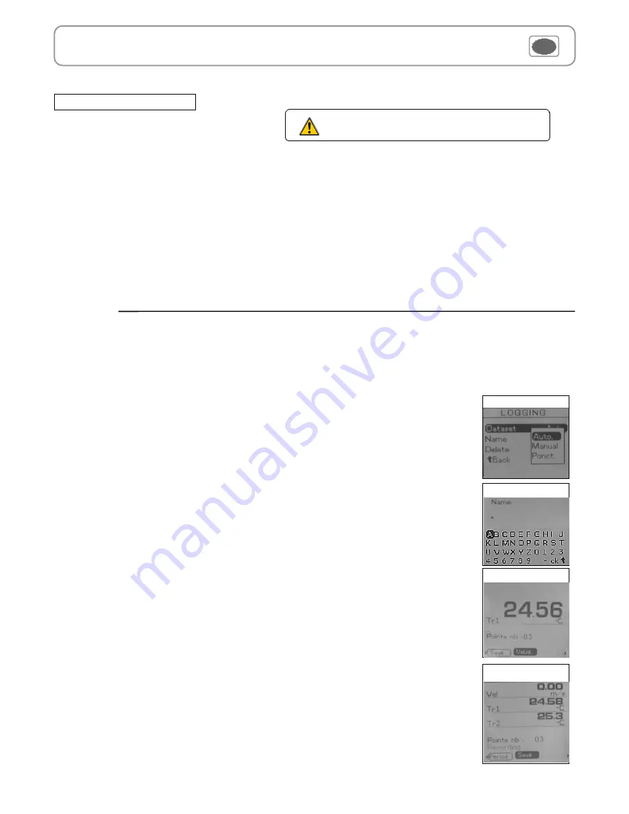
The Recording  menu allows a  measurement dataset. You can choose between a planned or a continuous dataset.
Memory capacity of the instrument is up to 

8,000

 points or 

50

 datasets.

A continuous dataset can be carried out using  VT200 and is composed of several dated measuring points. The 
operator can choose an automatic or a manual dataset, with an instant value or an average. This datasets can't be 
set using Datalogger-10 Software. 

Recording

manual dataset 

is composed of measuring points selected by the operator. 


a

. Click on 

OK 

or  

 to enter into sub function.

 b

. Select 

Manual 

 with 


and


. Confirm wih 

OK

.

 c

. Select 

Name 

 with 


and


. Confirm wih 

OK 

or  

.  Enter dataset name with  arrow keys 

 


and


e

. Confirm wih 

OK

.

 d.

 For measurement launching,  click on 

OK

 with the access key. The number of points selected and the 

parameter are displayed.

 e.

 To save your dataset  click on 

Save

 with the access key.

1. Create or launch a continuous  dataset 

1.1 Manual dataset

An 

automatic dataset 

is composed of measuring points with interval of time.

a

. Click on 

OK 

or  

 to enter  sub function.

b

. Select 

Auto. 

 with 


and


. Confirm wih 

OK

c

. Select 

Name 

 with 


and


. Confirm wih 

OK 

or  

.  Enter dataset name with the arrow keys 

 

  and


e

Confirm wih 

OK

.

d

. Enter dataset time  and  interval of time between 2 measurements by selecting 

Period

 with access key. Select 

Duration 

 or 

Interval 

with 


and


. Confirm wih 

OK

. Enter minutes and seconds  with arrow keys


and


( from 1 minute to 24 hours for the duration and from 5 seconds to 10 minutes for the interval). Confirm with 

OK

.

e.

 Select 

Start 

for dataset launching.

1.2 Automatic dataset

Select dataset

Enter name

Manual dataset

Automatic dataset

Configuration

Configuration sub-function allows to: :

 Select thermocouple

Click on 

OK 

or  

 to enter into sub function : a list of thermocouple available ( K, J or T type) appears .

Select type with  


and


. Confirm with 

OK

.

 Select display

Click on 

OK 

or  

 to enter into sub function. Select channel required with arrow keys 


and


 and confirm with 

OK

.  With 


and


. Select 

respectively 

ON 

or 

OFF 

with 


and


in order to enable or disable this function. Confirm with 

OK

 . 

 Select units

Click on 

OK 

or 

 to enter into sub function : a list of units available appears. For each channel, select unit required  with 


and


Confirm with 

OK

.

Click on 

Esc 

to return to previous screen.

If you use thermocouple probes, you must enter type 
into the Configuration sub-function.

Summary of Contents for VT 200

Page 1: ...Anemometer VT 200 Supplied with Calibration certificate ...

Page 2: ......

Page 3: ...Area 8 Duct type 8 Sizes 8 K2 factor 8 Units 9 Using Hotwire 9 Air velocity menu 9 Hold Min Max 9 Average 9 Point point average 9 Automatic average 9 Automatic point point average 9 Configuration 10 Thermocouple type 10 Display 10 Units 10 Recording 10 Parameters 12 Language 12 Date hour 12 Beep 12 Extinction 12 Contrast 12 Backlit 12 Key locking 12 Code 12 Downloading data 12 V General Informatio...

Page 4: ...0 to 80 C 0 3 of reading 0 25 C 0 1 C C F From 0 to 99 999 m3 h 3 of reading 0 03 area cm2 1 m3 h m3 h cfm l s m3 s m s fpm Km h Air velocity Temperature Airflow From 20 to 80 C 0 4 of reading 0 3 C 0 1 C C F From 0 to 99 999 m3 h 3 of reading 0 03 area cm2 1 m3 h m s fpm Km h Air velocity Temperature Airflow From 20 to 80 C 0 4 of reading 0 3 C 0 1 C C F From 0 to 99 999 m3 h 3 of reading 0 03 ar...

Page 5: ...r protection Top view Module connections mini Din C1 connector mini Din C2 connector Graphic display Hour Value Unit Circular menu Memory status used Battery level Keypad On Off key Access keys for circular meny Escape key Browsing joystick 4 directions Validation II Introduction ...

Page 6: ...s system Wire probes with Smart plus system are automatically recognized when connected to the instrument mini Din C1 connector mini Din C2 connector Probes are connected on min DIN connectors C1 and or C2 Wireless probe instrument communication Wireless communication between probe and instrument with automatic recognition after power up Secured Mini Din Connector Connections II Introduction Non e...

Page 7: ...asure Params Select a sub menu with access keys Measurement Communication interrupted Check probes connection Select a sub menu with access keys or with arrow keys 7 III Browsing Airflow measurement display Select sub menu with arrows keys or access keys Return to previous screen Air velocity measurement display Rec Hold Area Avg Params Veloci Config Rec Probe Config Airflow Params Avg Infos Probe...

Page 8: ...w probe information plugged to C2 Module C1 or wireless connections See Connections p 6 for more information about connections Available information are Sensor type Serial number Date of last calibration or adjustement Probes Status enabled ou disabled On enabled mode the probe is connected the measurement is carried out and the value is displayed On disabled mode the probe is connected the measur...

Page 9: ...Average This function allows to calculate the average value of various points that you can select Numbers of selected points and parameter for which calculation is carried out are displayed For adding a new measuring point to this calculation press OK to confirm If you click on average icon max and min values standard deviation average of each parameter and numbers of measuring points will be disp...

Page 10: ...to with and Confirm wih OK c Select Name with and Confirm wih OK or Enter dataset name with the arrow keys and e Confirm wih OK d Enter dataset time and interval of time between 2 measurements by selecting Period with access key Select Duration or Interval with and Confirm wih OK Enter minutes and seconds with arrow keys and from 1 minute to 24 hours for the duration and from 5 seconds to 10 minut...

Page 11: ...Preview of tables of points of datasets a Go to Recording menu b Select Display Click on OK to validate c Select dataset name with arrow keys et Click on OK to validate Summary screen of selected dataset is displayed From this screen you can Select other dataset using arrow keys t and u Display data of other channels using arrow keys p and q d Click on Mesure to display values table of selected da...

Page 12: ... Select language with arrow keys and and Confirm wih OK Language RF logging This sub function allows to enable or disable the RF Logging Click on OK or to enter into the sub function Select respectively ON or OFF with and in order to enable or disable this function Confirm wih OK This sub function allows to modify the backlit Click on OK or to enter Select your backlit level from 0 to 9 or AUTO wi...

Page 13: ...e 1 year guarantee for any manufacturing defect return to our After Sales Service required for appraisal Maintenance Warranty Info menu This menu allows to view the serial number of instrument and firmware version Battery When battery indicator flashes it is recommended to change the batteries 1 Remove the front part at the back of the instrument 2 Remove batteries 3 Insert new batteries AA LR6 1 ...

Page 14: ......

Page 15: ......

Page 16: ...tractual document We reserve the right to modify the characteristics of our products without prior notice Once returned to KIMO required waste collection will be assured in the respect of the environment in accordance to 2002 96 CE guidelines relating to WEEE ...

Reviews: