

8 PLZ2004WB/PLZ2004WHB
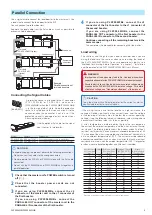
Cleaning the Dust Filter
A dust filter is installed on the inside of the louver on the front panel.
Periodically clean the filter to prevent clogging.
CAUTION
•
Clogged dust filters hinder the cooling of the inside of the
instrument and can cause a malfunction and shortening of the
service life.
•
When the Booster is in operation, air is sucked through the dust
filter to cool the load booster. If moister is included in the dust
filter, the temperature or humidity inside the Booster increases
and may cause a malfunction.
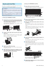
■
Cleaning the PLZ2004WB's dust filter
1
Remove the louver from the panel by placing a finger
on the 2nd level of the louver and pulling down the
1st level while pulling it toward you.
If the louver does not come off easily, pressing down the top
level of the louver will ease the work.
1st level
2nd level
2
Remove the dust filter from the inside of the louver
and clean it.
Remove the dust on the dust filter such as by using a vacuum
cleaner. If the filter is extremely dirty, clean it using a water-
diluted neutral detergent and dry it completely.
Dust filter
Louver
Tab
3
Attach the dust filter to the louver.
Firmly attach the dust filter so that the louver's tabs protrude out
of the top of the dust filter.
4
Attach the louver to the panel by pulling up on the
louver while holding the 2nd level of the louver with
your hand until the pin is fixed in place.
Pin
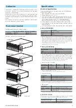
■
Cleaning the PLZ2004WHB's dust filter
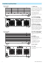
1
Remove the lower louver from the panel.
While lifting the bottom of the removal mark with your finger tips,
slide the entire louver to the right. Then, pull it toward you.
POWER
ELECTRONIC LOAD
PLZ2004WHB
2000W
5-650V
0-100A
①
②
②
While lifting the bottom of the removal mark with your finger tips (
①
),
slide the entire louver to the right (
②
).
Removal mark
Louver
2
Remove all the remaining louvers in the same manner
as was shown in step 1.
3
Remove the dust filter from the inside of the louver
and clean it.
There is a hook on the louver tab. Be sure not to get the dust
filter caught in the hook when removing the dust filter from the
louver.
Remove the dust on the dust filter such as by using a vacuum
cleaner. If the filter is extremely dirty, clean it using a water-
diluted neutral detergent and dry it completely.
Hook
Hook
Louver
Dust filter
Tab
Guide
4
Align the dust filter along the guide and attach it to
the louver.
Be sure to attach it firmly until the tab hooks of the louver
completely passes through the dust filter.
5
Attach the upper louver first.
Align the tab on the inner side of the louver to the panel groove
and slide the louver to the left to attach it. You can easily attach
the louver by aligning the long tabs (five locations) with the
grooves.
Tab (long)
Tab (short)
Upper louver
Groove for attaching the louver
Pass the long tabs on the back side of the louver through
the grooves on the panel indicated by circles.
Slide the louver to the left to lock the louver in place.
6
Attach all the remaining louvers in the same manner
as was shown in step 5.