RF-SFTP Wireless Base Set – Up
1. The smoke alarms and wireless base should be positioned as rec-
ommended in the installation guides supplied with the alarms
with special care to avoid possible causes of interference with the
RF signal(such other wireless products, electronic devices and
large metal objects).
2. The installation method for the alarms and base is described in
the smoke alarm installation manual for the alarms. All wiring
connections are made via the under side; the wireless base is
sealed and does not contain any user serviceable parts.
3. Bring house wiring through a dry lining box into back of alarm;
side entry, via mini trunking is also possible by carefully knib-
bling away edge on trim-plate. Make good joint, with white
sealant, if necessary. When installing the base using trunking, do
not attempt to break or knockout the sections out, use a tool to
cut them and prevent damaging the base.
4. Mains alarms and the mains powered RF-SFTP wireless base are
designed for installation by a competent, qualified electrician, in
accordance with the latest I.E.E. Regulations and complying with
relevant Building Regulations. Provide mains power to all units,
with which the rechargeable battery is turned on for service.
5. Care should be taken to insure the wires are pressed firmly into
the appropriate holes on the terminal block (Do not use slots for
wire retention, see figure d). Pull back lightly on each wire to
verify it is seated well.)
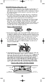
6. Verify that the power is on,the power is present when the amber and
green LEDs are illuminated. Choose a unit in a central location as the
master unit. This unit will enrol the other units(create a linked sys-
tem) during the remaining process; the remaining units will then be
remote units. Press the enrol button on the master unit until the
amber LED turns off (takes approximately 5 seconds) and begins to
flash on/off every 2 seconds with the green LED flashing every 4
seconds. (This indicates this unit is broadcasting as the MASTER
unit). THIS UNIT IS NOW THE MASTER WIRELESS BASE
FUNCTION BUTTON
ENROL BUTTON
ALARM RELEASE
LATCH
AMBER LED
ERROR INDICATOR
CEILING
ALARM
GREEN LED
POWER/TRANSMIT IND.
Figure 3. Side of Base with Alarm Attached
4
Figure 2, Terminal
Block
F
igure 1, Mounting Methods
1209-7201-02(21008418)_V2:_ 2011.4.19 9:13 AM Page 4


