© 2020 Carrier
1 / 6
P/N 3101069-EN • REV 005 • ISS 19OCT20
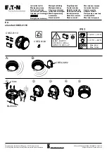
FX-PDD Duct Smoke
Detector Installation Sheet
Description
The FX-PDD Duct Smoke Detector is designed for use in duct
applications where temperatures can exceed standard detector
capabilities.
The device address is set using the two rotary switches located on
the front of the unit. One device address is required.
In installations where the controls and indicators are hidden from
view, a remote test station or an LED indicator can be connected to
the detector to provide these functions.
Jumper settings
The following jumper settings determine the operation of the
detector. See Figure 6 for proper jumper location.
Table 1: JP3 jumper settings
Setting
Description
Alarm
Configures the detector for alarm latching
operation.
Supervisory
Configures the detector for supervisory
operation.
This is the factory default setting.
LED operation
Two LEDs, visible from the front of the detector, show its status.
Table 2: LEDs
LED
Description
Power LED
Off when the detector is in the alarm state.
Flashes intermittently when the detector is in
the normal state.
Alarm/active LED
Indicates the detector is in the alarm/active
state.
Installation
WARNINGS
• The duct smoke detector is not intended as a substitute for open
area protection.
• This detector does not operate without electrical power. As fires
frequently cause power interruption, discuss further safeguards
with the local fire protection specialist.
• The duct smoke detector does not operate as designed outside
of the listed electrical and environmental specifications.
• The duct smoke detector does not sense smoke unless the
ventilation system is operating and the sensor’s cover is
properly installed.
• The duct smoke detector may not operate as designed unless
installed in accordance with these instructions and all applicable
national and local codes as determined by the local authority
having jurisdiction.
Note:
Read these instructions thoroughly before installing. Refer to
Application Bulletin P/N 3101107 for additional information regarding
installation instructions.
Installation guidelines
To ensure correct operation, install the duct detector using the
following guidelines:
• Install the duct smoke detector on a flat section of HVAC duct
between six and ten duct widths from any bends or obstructions.
• Install supply-side detectors at a point downstream from the
supply fan and after the air filter.
• Install return-side detectors at a point before the return air
stream is diluted by outside air.
Verifying the duct air velocity
In order to verify the airflow direction and velocity, air must be
moving through the HVAC system.
To verify the duct air velocity:
1. Drill a small hole at the point where the duct smoke detector is
being installed.
2. Using the SD-VTK Air Velocity Test Kit and a suitable air
velocity meter, verify that the air velocity in the HVAC duct falls
within the specified operating range of the detector and note
which direction the air flows.
3. If the air velocity does not fall within the specified range, relocate
the detector and seal the hole in the HVAC duct. Refer to
Application Bulletin P/N 3101107 for additional information
pertaining to installation locations.
firealarmresources.com