WX
10000.1
Technical
Manual
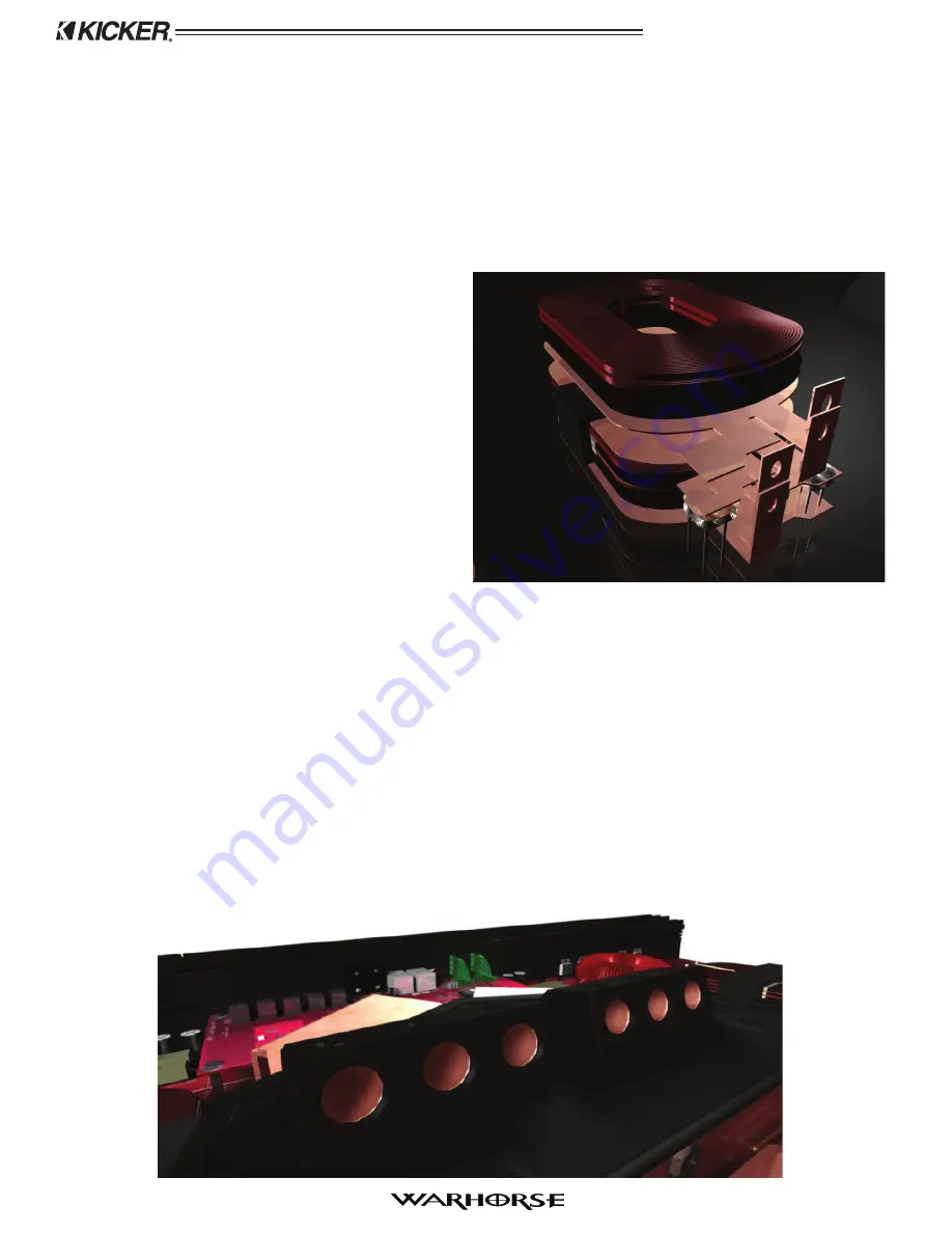
There are fi ve extremely good reasons why the Planar design is best for the Warhorse.
By design, a Planar style of transformer has the lowest leakage inductance. This is very important
1.
from an engineering standpoint because of the extremely high current level needed to produce 10,000
Watts. The coupling between the primary and secondary is much better than with any other design.
They have an ultra low profi le for the electrical rating. With the winding being fl at and glued to
2.
the ferrite core the transformers are very tough. The primary windings are screwed to the buss bars,
increasing stability and providing reliable high-current connections.
Since they have the best surface-to-volume
3.
ratio, cooling is better than that of conventional
toroidal transformers.
With other types of transformers, it is diffi cult
4.
to get consistent properties relating to the
wrapping of the windings. The physical layout
of the Planar transformer allows it to be built the
same way each time for very consistent results.
A high turn ratio is impractical with the other
5.
transformer designs. In the Planar transformer we
can easily reach the 19:1 ratio needed to get the
voltage used in a 10,000 Watt amp.
The switching frequency is 24 KHz, yielding a much easier to fi lter 48 KHz ripple after the full wave
rectifi ers. The output of this signal-modulated power supply is fi ltered by two over-built toroidal output
coils. Spike suppression is accomplished with fi lters utilizing eight 35 Watt snubber resistors. Worst case
for these fi lters is seen at full output.
The printed circuit board (PCB) for an amplifi er this large has to be stronger than normal. The Kicker
Warhorse components are mounted on a thicker (.090”, 2.5 mm) than usual fi berglass PCB with much
heavier (4 ounce) copper traces.
In order to optimize the circuit board layout the battery power connectors needed to be near the top
center of the amplifi er chassis. There are three 1/0 gauge sized proprietary gold plated brass connectors
for the negative ground connections and three more for the positive connections. These connectors are
bolted to symmetrical copper buss bars for power distribution within the chassis.
3


