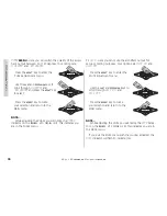
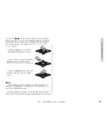
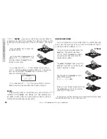
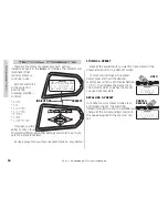
background image

37

SX .1 Series Amplifiers

Warran

ty

ELECTRONICS LIMITED WARRANTY

WHAT IS NOT COVERED?

Kicker warrants this product to be free from defects in material and workman-

ship under normal use for a period of 

90 DAYS

from date of original purchase

with receipt. When purchased from an Authorized KICKER Dealer it is warranted
for

TWO (2) YEARS

from date of original purchase with receipt. If the product

is labeled “B S

Stock” it is warranted for 90 D

DAYS from date of original purchase

with receipt. If labeled “B S

Stock” and purchased from an Authorized KICKER

Dealer, it is warranted for ONE ((1) Y

YEAR from date of purchase with receipt. In all

cases you must h

have the original rreceipt! Should service be necessary under this

warranty for any reason due to manufacturing defect or malfunction during the
warranty period, Kicker will replace or repair (at its discretion) the defective mer-
chandise with equivalent merchandise at no charge. Warranty replacements on
“B-Stock” merchandise may have cosmetic scratches and blemishes.
Discontinued products may be replaced with more current equivalent products.

This warranty is valid only for the 

original purchaser

and is not extended to

owners of the product subsequent to the original purchaser. Any applicable
implied warranties are limited in duration to a period of the express warranty as
provided herein beginning with the date of the original purchase at retail, and
no warranties, whether express or implied, shall apply to this product thereafter.
Some states do not allow limitations on implied warranties, therefore these
exclusions may not apply to you.

This warranty gives you specific legal rights; however you may have other

rights that vary from state to state.

WHAT TO DO IF YOU NEED WARRANTY OR SERVICE

Defective merchandise must be returned to your local Authorized Stillwater

Designs (Kicker) Dealer for warranty. Assistance in locating an Authorized Dealer
can be obtained by writing or calling Stillwater Designs direct. You can confirm
that a dealer is authorized by asking to see a current authorized dealer window
decal.

If it becomes necessary for you to return defective merchandise, call the

Kicker Customer Service Department at (405)624-8510 for a Return Authorization
(RMA) number. Package all defective items in the original container or in a pack-
age that will prevent shipping damage, and return to

Stillwater Designs, 5021 North Perkins Road, Stillwater, OK 74075

The RMA number must be clearly marked on the outside of the package.

Return only defective components. Return of entire cabinets, system packs,
pairs, etc. increases your return freight charges. Non-defective items received
will be returned freight collect.

Include a dated

proof-of-purchase

stating the Customer name, Dealer

name, product purchased and date of purchase. Warranty expiration on items
without proof-of-purchase will be determined from type of sale and the manu-
facturing date code. Freight must be prepaid; items received freight collect will
be refused.

Failure to follow these steps may void your warranty. Any questions can be

directed to the Kicker Customer Service Department at (405)624-8510.

This warranty is valid only if the product is used for the purpose for which it

was designed.

It does not cover:

Kicker strives to maintain a goal of 24-hour service for all returns.

Delays may be incurred if lack of replacement inventory or parts is
encountered.

Contact your International Kicker dealer or distributor concerning specific 

procedures for your country’s warranty policies.

• Damage due to improper installation.
•  Subsequent damage to other components.
•  Damage caused by exposure to moisture, excessive heat, chemical cleaners, 

and/or UV radiation.

•  Damage through negligence, misuse, accident or abuse. Repeated returns for

the same damage may be considered abuse.

•  Any cost or expense related to the removal or reinstallation of product. 
•  Speakers damaged due to amplifier clipping or distortion.
• Items previously repaired or modified by any unauthorized repair facility.
• Return shipping on non-defective items.
•   Products with tampered or missing barcode labels.
• Products returned without a Return Authorization (RMA) number.
• Freight Damage.
• The cost of shipping product to Kicker.
• Service performed by anyone other than Kicker.
• Speaker with any foreign caulk used for gasket material.

HOW LONG WILL IT TAKE?

INTERNATIONAL WARRANTY

P.O. Box 459 • Stillwater, Oklahoma 74076 • U.S.A. • 405 624-8510

KICKER drivers are capable of producing sound levels
that can permanently damage your hearing! Turning
up a system to a level that has audible distortion is
more damaging to your ears than listening to an
undistorted system at the same volume level. The
threshold of pain is always an indicator that the sound
level is too loud and may permanently damage your
hearing.
Please use common sense when controlling volume!

WARNING:

April 2003

Summary of Contents for Livin Loud SX1250.1

Page 1: ......

Page 2: ...Where Purchased Purchase Date Amplifier Model Number Amplifier Serial Number Congratulations You have just purchased the latest in amplifier technology to carry the famous KICKER name Your KICKER SX series amplifier employs the lat est in DSP signal processing to give you total control over your sound Like all KICKER prod ucts it is designed and built to give you years of powerful and trouble free...

Page 3: ... frequency and variable boost or cut Q range 5 10 in 5 steps Center frequency 20 Hz 200 Hz in 1 Hz steps Boost or cut range 18 dB Adjustable Phase The output phase polarity can be set at 0 Degrees or 180 Degrees UltraMatch Gain Structure Digital input gain control with five selectable gain ranges 1 volt 2 volt 4 volt 8 volt 16 volt with 12 dB of adjustment in each range in 5 dB steps SickBay and O...

Page 4: ...AD M1 M2 M3 M4 ESC ENT HOME SYS MEM 1 GAIN EQ LPF HPF KOMP AMP1 LOCK MEM 2 MEM 3 MEM 4 PHASE MUTE AMP2 LEFT RIGHT kicker ISIS VFD ISIS KEYPAD Here is a brief description of the indicators found on the VFD 03 Indicates amplifier 1 is selected for adjustment Only available in four channel amps 03 Indicates amplifier 2 is selected for adjustment Only available in four channel amps 2 Indicates the amp...

Page 5: ...d to select memory preset 1 or to store cur rent settings into preset 1 0 Used to select memory preset 2 or to store current settings into preset 2 0 Used to select memory preset 3 or to store current settings into preset 3 0 Used to select memory preset 4 or to store current settings into preset 4 6 Used to exit the current menu 17 Used to enter the selected menu 20 Used to return to the Main men...

Page 6: ...d RCA input connectors and PAST jacks provide solid input and output connections for your pre amp signal Speaker Speaker Left Input Left PAST Right Input Right PAST BLAST Port In BLAST Port Out X X X X Ground Remote 12 Volt Fusing Power LED Check Fuse LED Custom machined power block accepts up to a 2 Ga wire for both power and ground connections and up to an 8 Ga for remote turn on assures maximum...

Page 7: ...ting the amp in the passenger compartment will allow cooler operation Remember that the controls on top of the amp will need to be accessible for adjustment later Keep this in mind as you choose your amplifier s mounting location Now that you are ready to mount your amplifier use the supplied 3mm allen wrench to remove the amplifier EndKaps This will give you access to the mounting holes in the am...

Page 8: ...onnections This wire should be as short as possible 24 inches or less and connected to a paint corrosion free solid metal area of the car s chassis Use the same gauge wire as recommended for the amplifier s power connection to the battery Adding an additional ground wire between the car battery s negative post and the car chas sis of this same gauge or larger is also recommended If you ever need t...

Page 9: ...2 GAINEQ LPF HPF PHASE KOMP 8 8 8 8 8 8 8 8 8 8 M2 M3 M4 SIGNAL OUT SIGNAL IN MULTIPLE SPEAKERS OR VOICE COILS PARALLEL WIRED SX 1 series amplifiers are capable of powering multiple speakers or voice coils wired in parallel as long as the minimum impedance does not drop below 2 ohms SX650 1 or 1 ohm SX1250 1 GROUND REMOTE TURN ON BATTERY 12V FUSE 18 or less S S ESC HOME ENT M1 AMP 1 LOCK LEFT SYS ...

Page 10: ...T M1 AMP 1 LOCK LEFT SYS RIGHT MUTE AMP 2 GAINEQ LPF HPF PHASE KOMP 8 8 8 8 8 8 8 8 8 8 M2 M3 M4 SIGNAL OUT SIGNAL IN _ _ _ These are just a few of the many ways you can use your SX 1 series Kicker amplifier These system diagrams are designed to give you a basic understanding of the most com mon uses for this amplifier For more complex systems please visit your local authorized Kicker dealer You c...

Page 11: ...when strapped 1 Wire both amplifiers to 12 volt power ground and remote 2 Connect a RCA cable from the source unit to the RCA Input jacks on the primary amp 3 Use the supplied 1 8 inch mono cable to connect the Amp Strapping Out jack of the primary amplifier to the Amp Strapping In jack of the secondary amplifier 4 Use a short piece of heavy gauge wire 12Ga 10Ga 8Ga to connect the Speaker negative...

Page 12: ...put level of both the amplifiers that are strapped together 1 Mount the Remote Bass Level Controller in the front of your vehicle and plug in the supplied cable 2 Route the supplied cable to the primary amplifier and connect to its BLAST In jack 3 Enjoy BACK VIEW SIDE VIEW Mounting Surface SUPPLIED CABLE AMP STRAPPING AMP STRAPPING SOURCE UNIT _ ...

Page 13: ...lifier or processor without the need for Y cables The signal from the PAST jacks is identical to the signal fed to the amplifier via its RCA input jacks and is not affected by any of the amplifier s built in digital signal processing Most head units with high voltage outputs should be capa ble of driving up to ten amplifiers in a chain SOURCE UNIT AMP STRAPPING AMP STRAPPING To Next Amplifier or P...

Page 14: ... place Route the cable from the controller to the BLAST input jack on the amplifier chassis That s it If you wish to control more than one amplifier with your remote you will simply need to use a RJ45 cable not supplied but available at any Radio Shack computer store or electronics center to connect the BLAST output jack of the first amp to the BLAST input jack of the next amplifier SOURCE UNIT To...

Page 15: ...els and each one of these menu levels can have an infinite number of its own items Navigating this simple menu structure is very easy using the 5 way keypad You use the 83 and 2 1 keys to scroll through the available menu items and the 17 key is used to select that menu item The 6 key backs you up one menu level from where you are and the 20 key can return you all the way to MAIN MENU by pressing ...

Page 16: ...d with in the MAIN MENU no mat ter how deep in the menu level struc ture you are Pretty cool This is a very quick way to return to the MAIN MENU after drilling down several menu layers to view or change an item When adjusting any amplifier control the 83 and 2 1 arrow keys have 2 speeds normal and accelerated Pressing and releasing the key repeatedly will scroll through the menu items at normal sp...

Page 17: ...ame you have changed it to If you want to freeze the scrolling display simply press the 20 key and the scrolling will stop Now you can manually select the item you wish to have displayed by using the 83 or 2 1 keys If you want the display to continue scrolling simply press the 20 key again MAIN This menu is the first menu accessed from the DEFAULT menu and is the gateway to all the settings and in...

Page 18: ...ion in 1 10th of an hour increments 7 Sick Bay Contains several diagnostic tools Once in this menu you use the 83 and 2 1 keys to scroll through CURRENT HISTORY and PINK NOISE options Press the 17 key to select 7a CURRENT shows amplifiers current status or fault code The 6 possible codes are normal No problem normal operation thermal Thermal cutoff protection engaged short Short circuit protection...

Page 19: ...blinking as a reminder HOME ENT ESC SYS MEM 1 GAIN EQ LPF HPF KOMP AMP1 LOCK MEM 2 MEM 3 MEM 4 PHASE MUTE AMP2 LEFT RIGHT noise on HOME ENT ESC 8 Amp Name Here you can assign a unique name to your KICKER SX amplifier This name will replace the model name in the DEFAULT screen If you change your mind and do not want to change the name press and hold the 20 key for 1 5 seconds BEFORE making any chan...

Page 20: ...is feature is currently not used but is reserved for future expansion 11 Gain Range Sets the input voltage window of the UltraMatch gain control Possible choices are 1V 2V 4V 8V 16V Select the one closest to the maximum RCA input voltage you expect to send to the amplifier Use the 83 and 2 1 keys to select your voltage Press the 6 to return to the MAIN menu 12 Bypass DSP Bypasses all DSP processin...

Page 21: ...SAVER Option to turn on or off the screensaver When on AUTO the display will go to sleep when there is no button activity for 60 seconds Pressing any button once will wake up the display The OFF selection turns off the screensaver and the display is always on 15 Lock Code Set your own lock code The factory default is 123 but you can change it and create your own code with up to 10 characters The 6...

Page 22: ... gain indicator on the ISIS VFD display is lit This indicates you are in the GAIN menu 16 Reset Amp This option resets all adjustable settings back to their original factory defaults Use the 83 and 2 1 keys to select SKIP RESET or DO RESET and then press the 17 key to perform the selected action 17 About This menu item will display information about the DAP Digital Audio Processor hardware softwar...

Page 23: ...imple terms lower Q effects more frequencies around the center frequency while higher Q effects fewer frequencies around the center frequency Use the 83 and 2 1 keys to select your Q value Press the 6 to return to the EQ menu BOOST CUT is how much you want to boost or cut the equalizer and has a range of 18 dB to 18 dB in 5 dB steps Use the 83 and 2 1 keys to boost or cut the EQ and then press the...

Page 24: ...to 48 dB in 6 dB steps Use the 83 and 2 1 keys to select your slope Press the 6 to return to the LO PASS menu NOTE While adjusting the low pass crossover you will notice the LPF indicator on the ISIS VFD display is lit This indicates you are in the LO PASS crossover menu The KICKER SX amplifier monitors and prevents any low pass crossover point from being any closer than 1 3 octave from the high p...

Page 25: ...F to 24 dB in 6 dB steps Use the 83 and 2 1 keys to select your slope Press the 6 to return to the HI PASS menu NOTE While adjusting the high pass crossover you will notice the hpf indicator on the ISIS VFD display is lit This indicates you are in the HI PASS crossover menu The KICKER SX amplifier monitors and prevents any high pass crossover point from being any closer than 1 3 octave from the lo...

Page 26: ...VFD display is lit This indicates you are in the PHASE menu 7 Mute Here you can mute the amplifier s output for setup or testing purposes Your options are MUTE ON and MUTE OFF Press the 17 key to enter the MUTE adjustment menu Use the 83 and 2 1 keys to scroll through MUTE ON and MUTE OFF Press the 6 key to make your selection and return to the MAIN menu NOTE While adjusting the MUTE you will noti...

Page 27: ...ter the KOMPRESSOR adjustment menu Once in this menu use the 83 and 2 1 keys to scroll through RED LINE contour attack and OFF Press the 6 key to accept your selection and return to the MAIN menu NOTE While adjusting the Kompressor you will notice the KOMP indicator on the ISIS VFD display is lit This indicates you are in the KOMPRESSOR menu See the specifications pages for a brief description of ...

Page 28: ...is indicates your amplifier is locked down and will require a code to unlock it before any adjustments can be made HOME ENT ESC UNLOCK AMPLIFIER You do remember your lock code right You better because that is now the only way in If you have not changed it then it is still at the factory default of 123 To unlock your amplifier press the 17 key The display will show UNLOCK Press the 17 key again You...

Page 29: ... your amplifier this more than likely means means you have forgotten your lock code You will need to call KICKER directly at 405 624 8583 to handle this situation You will need your amplifier s serial number AND your receipt as the guys and gals answering the phone will need this information from you to help you out So before you call gather this information up and have it ready to save us some ti...

Page 30: ...ASE MUTE AMP2 LEFT RIGHT kicker INDICATORS PRESETS STORING A PRESET Make all the adjustments you want to have stored in the preset and return to the DEFAULT screen To store your settings into a preset simply press and hold the desired memory key until the VFD display flashes STORED Then release the memory key The indicator which matches the preset you used will illuminate RECALLING A PRESET To rec...

Page 31: ...0 DB 0 DB 0 DB 0 DB In more general terms each preset offers you these options Memory 1 sets the amplifier up with a 24 dB per octave low pass crossover at 80 Hz and an infrasonic filter often called subsonic filter to protect the speakers from harmful ultra low frequencies Memory 2 sets the amplifier up with a 24 dB per octave low pass crossover at 80 Hz an infrasonic filter often called subsonic...

Page 32: ...r signal on RCA cable with VOM in AC position Substitute known good source unit If amp does not make noise using PINK NOISE then Check speaker connections Test speaker outputs with known good speaker Other S Symptoms Amp is very hot no output Thermal protection is engaged Check SICK BAY to verify Check for proper impedance at speaker terminals Also check for adequate airflow around amplifier Amp s...

Page 33: ... too high CAUTION When jump starting the vehicle be sure that connections made with jumper cables are cor rect Improper connections to to will result in blown amplifier fuses as well as failure to other systems in the vehicle If you have more questions about the installation and oper ation of your new KICKER amplifier see the Authorized KICKER Dealer in your area You may also call our Technical Se...

Page 34: ...y Red line Provides a quick clamp to dynamic peaks while still allowing a full sound to come through Effect increases at higher volume levels Like to play it loud but want to protect your speakers Want low level details to come through over road noise Want a more even volume level to your music All can be achieved with this preset OFF Pretty much says it all This turns the KOMPRESSOR off This is t...

Page 35: ... x 1 na 13 8V 2 Mono 1 5 THD 650 x 1 625 x 1 13 8V 1 Mono 1 5 THD na 1250 x 1 Dynamic Power In Watts All Channels Driven 14 4V 4 Mono 1 5 THD 325 x 1 na 14 4V 2 Mono 1 5 THD 650 x 1 625 x 1 14 4V 1 Mono 1 5 THD na 1250 x 1 Length With EndKaps 16 22 50 40 64cm 57 15cm Fusing 30A x 2 150A x 1 external Recommended Power Ground Wire 4 GA 2 GA ...

Page 36: ... Freq 10 Hz 60 Hz in 1 Hz steps High Pass Crossover Slope 0 off 24 dB in 6 dB steps Low Pass Crossover Freq 30 Hz 200 Hz in 1 Hz steps Low Pass Crossover Slope 0 off 48 dB in 6 dB steps KickEQ Frequency 20 Hz 200 Hz in 1 Hz steps KickEQ Bandwidth Q 5 to 10 in 5 steps KickEQ Boost Cut 18 dB per Octave Remote Bass Level Control Included with each amplifier Power Ground Terminals Will accept up to 2 ...

Page 37: ... prevent shipping damage and return to Stillwater Designs 5021 North Perkins Road Stillwater OK 74075 The RMA number must be clearly marked on the outside of the package Return only defective components Return of entire cabinets system packs pairs etc increases your return freight charges Non defective items received will be returned freight collect Include a dated proof of purchase stating the Cu...

Page 38: ...38 SX 1 Series Amplifiers Notes Notes Pizza Delivery ...

Page 39: ...39 SX 1 Series Amplifiers Notes Chic s Numbers Hook Ups ...

Page 40: ......

Page 41: ......

Page 42: ......

Reviews: