Kichler Lighting Design Pro 15DC100 Instruction Manual Download Page 6


Connecting fixtures to the Kichler Design Pro LED Controller 

The value of the multi-zone feature of the Design Pro LED Controller lies in the ability to individually control defined areas of the landscape lighting 

design. The system design should take this feature into consideration. Lighting at pre-defined areas (zones) should be connected to a trunk line or 

lines that will then be powered by the PSU Zones. Trunk lines that control individual zones are then connected to one of the PSU Zone terminal 

blocks. 


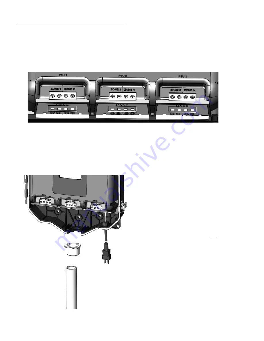
Each PSU (Power Supply Unit) has a pair of zones (PSU1 is zones 1 and 2, PSU2 is zones 3 and 4, and PSU3 is zones 5 and 6) and each PSU is 

capable of 100W (6.7 amps at 15VDC).  Any pair of zones can be loaded to a maximum of 100W regardless of how the 100W is split.  For 

example: Zone 1 can have 80W and Zone 2 can have 20W. 


Each zone is also capable of having multiple wire runs provided the 100 Watt per PSU limit is not exceeded.  Use wattage value (not VA) provided 

for each fixture to calculate the load on the Controller.  There are no minimum load or polarity requirements for loading the Controller. 


1) Once the fixture locations/zones have been determined, the trunk-line cable should be routed to the fixtures and connected according to the 

instructions provided with the fixtures.  Use wattage value (not VA) provided for each fixture to calculate the load on the Controller.  There are no 

minimum load requirements for any zone or PSU. 

2.) At the Kichler Design Pro LED Controller, route the cable(s) through the conduit adaptor.   Note: For a more professional install, the secondary 

trunk lines can be routed through an 18" length of 1" or 1-1/4" trade size PVC conduit (not provided) prior to routing through the conduit connector.   


3) Split the 18/2, 16/2, 14/2, 12/2, 10/2 or 8/2 trunk-line cable 

approximately 3”, and strip 3/8” [10mm] insulation off each 

wire.   On the bottom of the terminal block push one bare wire 

into the hole marked “+” of the appropriate zone.   

4) Tighten the corresponding screw on terminal block face until 

wire is secure.  Push remaining bare wire of the same run into 

the “-” hole on bottom of terminal block and tighten terminal 

screw.  Screw terminals should be tightened to 12.5 lb-in [1.4 

N-m]. 

5) Repeat steps for all runs and all zones. 

6) Plug power supply cord into standard 115/120 volt 

receptacle. 

NOTE:

 The power supply cord must be plugged 

into a weather  tight receptacle equipped with a Ground Fault 

Circuit Interrupter (GFCI). 


Conduit Adaptor (fits 1" or 1-1/4" 
trade size PVC conduit) 


PVC Conduit (optional, not supplied) 

Tools Required: #1 or #2 Phillips or 1/4" flat head screwdriver


Summary of Contents for Design Pro 15DC100

Page 1: ...French and Spanish language versions of these instructions please go to www kichler com Para las versiones en franc s y espa ol de estas instrucciones por favor consulte www kichler com Pour les vers...

Page 2: ...er supply 5 Mounting the power supply 5 Connection of fixtures 6 Manually operating the power supply 7 Quick Start Set up 7 Reviewing and Customizing Schedules 8 System settings 9 Z Wave Network setti...

Page 3: ...Mounting bosses 8 Wire routing adaptor 4 Terminal block 9 Housing cover latches 5 Security lock tab 10 Reset button 11 Zone ports 12 Conduit knock out 13 Wire adaptor catch 14 Cover 15 Tapered keyhol...

Page 4: ...u button LCD Display Graphical interface for user input and feedback Reset button Resets all hardware and software to factory settings Enter button User button for sending input to the CPU Navigation...

Page 5: ...tion should be taken for the requirements listed above 2 The mounting location should be in a well ventilated area that is away from sprinklers and irrigation spray 3 The mounting location should be s...

Page 6: ...be routed to the fixtures and connected according to the instructions provided with the fixtures Use wattage value not VA provided for each fixture to calculate the load on the Controller There are no...

Page 7: ...rest city to enable the preset programs 1 Quick start guide to set language geographical location date and time 1 The initial factory setting is English to change Controller to French or Spanish press...

Page 8: ...ion button or use the down navigation button to scroll to Go Back and press Enter 5 Important Press Home System Settings Save Settings This will save the most recently modified settings of the Control...

Page 9: ...k all wiring and fixtures to remove any faults on the system identified on the Display Faults screen see 3 above 2 Press Home System Reset Faults Then press Enter 3 Manually restart the zone s where t...

Page 10: ...and all other Controllers the ones being added will become Subservient Controllers A maximum of 4 total controllers One master and up to 3 subservient can be on one network Certain features such as t...

Page 11: ...ious menu 8 For ease of installation of multiple Controllers on a property one Controller can transmit the Initial Setup data to multiple Controllers in the network 1 Set the Time Date and Location fo...

Page 12: ...Continue Choosing the Select All option will assign all Zones of all Controllers to the button press 11 Select the Zone or Zones on the first Controller Controller1 Zones to be assigned to the button...

Page 13: ...roller but not sent to the Power Unit zones until the 10 seconds have elapsed 2 When installing a run of fixtures onto a zone it is recommended that the trunk line is attached to the terminal block pr...

Page 14: ...ed on a Z Wave network but only one Motion Sensor can be setup to manage a DC Controller In other words a Controller cannot have multiple Motion Sensors instructing it but a Motion Sensor can manage m...

Page 15: ...ur in a particular installation If this equipment does cause harmful interference to radio or television reception which can be determined by turning the equipment off and on the user is encouraged to...

Page 16: ...16 Menu Tree Flow Diagram...

Page 17: ...17 Menu Tree Flow Diagram continued...

Page 18: ...18 IS 15DC300 US English Date Issued 6 12 15...

Reviews: