background image

[

键入文字


Conversion to LP gas orifice 

1.


Take out the screws on the top cover, then take off the top cover. You can see the orifice is on the 
left side of the Cheese melter as below 

Fig.7 

shows. 


Fig.7                                         Fig.8 


2.


As Fig. 8 shows, unscrew and remove the Nat. gas orifice [#31(φ3.2mm)] turning counter-clockwise, 
then screw in the LP gas orifice *#52(φ1.68mm)+ clockwise.  


3.


Change the pressure regulator spring kit to LP gas model, set at 10" W .C. (Water Column).  


Fig.9,                      Fig.10 


4.


Turn pilot adjustment screw clockwise, then light standing pilot and adjust flame to be 1/4" high. 


A product with the KFE incorporates the best in durability and low maintenance. We all recognize, 
however, that replacement parts and occasional professional service may be necessary to extend the 
useful life of this unit. When service is needed, contact a KFE Authorized Service Agency, or your dealer. To 
avoid confusion, always refer to the model number, serial number, and type of your unit. 


Summary of Contents for KF-CMG-36

Page 1: ...USTMENT ALTERATION SERVICE MAINTENANCE CAN CAUSE PROPERTY DAMAGE INJURY OR DEATH READ THE INSTALLATION OPERATING AND MAINTENANCE INSTRUCTIONS THOROUGHLY BEFORE INSTALLING OR SERVICING THIS EQUIPMENT Please call the Service Department and ask for contact information for your local service company ...

Page 2: ...NED FROM THE LOCAL GAS SUPPLIER IMPORTANT IN THE EVENT A GAS ODOR IS DETECTED SHUT DOWN UNITS AT MAIN SHUT OFF VALVE AND CONTACT THE LOCAL GAS COMPANY OR GAS SUPPLIER FOR SERVICE FOR YOUR SAFETY DO NOT STORE OR USE GASOLINE OR OTHER FLAMMABLE VAPORS OR LIQUIDS IN THE VICINITY OF THIS OR ANY OTHER APPLIANCE WARNING IMPROPER INSTALLATION ADJUSTMENT ALTERATION SERVICE OR MAIN TENANCE CAN CAUSE PROPER...

Page 3: ...Page 11 INSTALLATION Before installing verify that the type of gas supply natural or propane agrees with the specifications on the rating plate located underneath the Cheese melter rack drip tray If the supply and equipment requirements do not agree do not proceed with the installation Contact your dealer immediately UNPACKING Immediately after unpacking check for possible shipping damage If the C...

Page 4: ...471 NOTE In the Commonwealth of Massachusetts Al l gas appliances vented through a ventilation hood or exhaust system equipped with a damper or with a power means of exhaust shall comply with 248 CMR 3 NFPA Standard 96 Vapor Removal from Cooking Equipment latest edition available from the National Fire Protection Association Batterymarch Park Quincy MA 02269 In Canada 1 Local codes 2 CAN CSA B 149...

Page 5: ...g gas should be fully purged to remove air GAS PRESSURE REGULATOR INSTALLATION Gas regulator pressure is preset at 5 Water Column W C for natural gas and 10 W C For propane gas Minor adjustments may be required based on site specific gas pressure Install the regulator as close to the Cheese melter on the gas supply line as possible Make sure that the arrow on the underside of the regulator is orie...

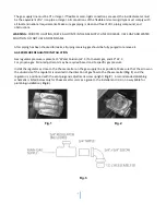
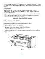
Page 6: ...btained from the standard f or Vapor Removal from Cooking Equipment NFPA No 96 latest edit ion available from the National Fire Protection Association Batterymarch Park Quincy MA02269 WALL MOUNTING OF CHEESE MELTER For Cheese melter to be mounted on a Wall Fig 4 The separate wall mounting bracket accessory will be needed to wall mount the unit 1 Place mounting bracket balloon 3 and screws provided...

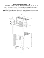
Page 7: ...nted over a gas range WHICH IS DESIGNED SPECIFICALLY TO RECEIVE THIS KFECHEESE MELTER it must be installed according to the instructions below Using the twelve bolts provided balloon 1 install mounting brackets balloon 2 on both top mounting posts balloon 3 See photos below to show how to install posts on range back Fig 6 ...

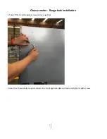
Page 8: ...8 Cheese melter Range back installation 1 Take off the 12 self tapping screws on the range back 2 Insert the Cheese melter support column into the Range back plate as shown and tighten it with screws ...

Page 9: ...9 3 Lift Cheese melter and attach it to the proper position of the support column ...

Page 10: ...10 4 Take two brackets out of the package ...

Page 11: ...11 5 Attach Cheese melter mounting track to the appropriate screw according to the hole position and tighten all screws ...

Page 12: ...12 ...

Page 13: ...lter to cool 2 To remove Cheese melter rack for cleaning adjust Cheese melter rack to center position 3 Position left and right hands simultaneously on edges of Cheese melter rack and raise both rack stops 4 Slide Cheese melter rack and drip tray forward past rack stops which must be pivoted out of the way holding tray up against racks 5 Remove Cheese melter rack and drip tray from Cheese melter 6...

Page 14: ... 键入文字 14 ...

Page 15: ...sure regulator spring kit to LP gas model set at 10 W C Water Column Fig 9 Fig 10 4 Turn pilot adjustment screw clockwise then light standing pilot and adjust flame to be 1 4 high A product with the KFE incorporates the best in durability and low maintenance We all recognize however that replacement parts and occasional professional service may be necessary to extend the useful life of this unit W...

Page 16: ...N FORM Fill in the blanks and keep this paper with the original invoice in a safe place for future service purpose 1 Date of purchase ____________________________________ 2 Model No ____________________________________ 3 Serial No ____________________________________ Your notes ...

Reviews: